This came up on the github before, and I pointed this out:
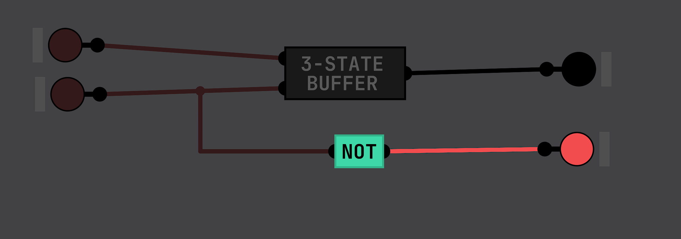
Since you always have access to the thing that determines if a 3-state buffer is connected, you can always hook into that and negate it to get a "isDisconnected" signal.
Wanting keyboard navigation is not an unreasonable ask. Saying "Just get a mouse" is a really dismissive "solution" - and "Learn git, C#, and unity and then digest the ins and outs of the codebase, just so you can have keyboard navigation" is even moreso. Some folks don't like mice, and for some it's even impractical - to say nothing of the actual accessibility concerns.
Using arrow keys for keyboard navigation is *probably* fairly low-impact, doesn't interfere with any existing functionality, and makes for a better user experience for some.
Okay, sure, it's probably not a huge segment of the playerbase, but despite that, to say "No. Deal with it." to a reasonable request *when you aren't even the developer* is a really crappy thing to do.
Heck, I *am* a mouse user, and I would love to have keyboard navigation that would effectively pan by a screen's worth of distance, too.
Delete this. You've already tried contacting him and also made two topics about contacting him. Don't follow him around the forums badgering him on unrelated posts, too.
1 = 5v (or 3.3v in your example) and 0 = 0v (or 1v in your example) isn't quite true and is a big oversimplification.
When a chip asserts a 1, it is actively connecting its output to VCC, and when a chip asserts a 0 it is actively connecting its output to GND. When no value is asserted on a bus, its not that it *actively* has 0 volts on it, it is that nothing is putting a value on it - that's what they mean by it "floating" - it could have some voltage potential relative to ground because nothing is anchoring it to VCC or GND. but that voltage isn't being asserted - its noise - and that noise is indistinguishable from some value if a chip tries to read from it.
Because of that, you can't really use any logic gate to determine if something is asserting something onto the bus from the receiving end - that's what control signals are for.
You can right-click an output of an instance of a chip, and set the color there - output pin objects will inherit their color from that wire, and it'll work its way through when you package up the current chip.
I think the underlying shortcoming here is not that the ROM is too small, but that you can't access the right-click menu of an inner ROM chip from an outer chip, and that each outer chip (I think) would retain the state of the initial inner ROM.
This prevents people from stringing together multiple ROMs into a bigger custom ROM chip.
You can change the color of pins and chips and the size of chips already. hit Customize when you go to save a chip. For pins, right-click on an IN pin to change the color, or the out pin of an instance of a chip to change the wire's color - the connected node will inherit from that.
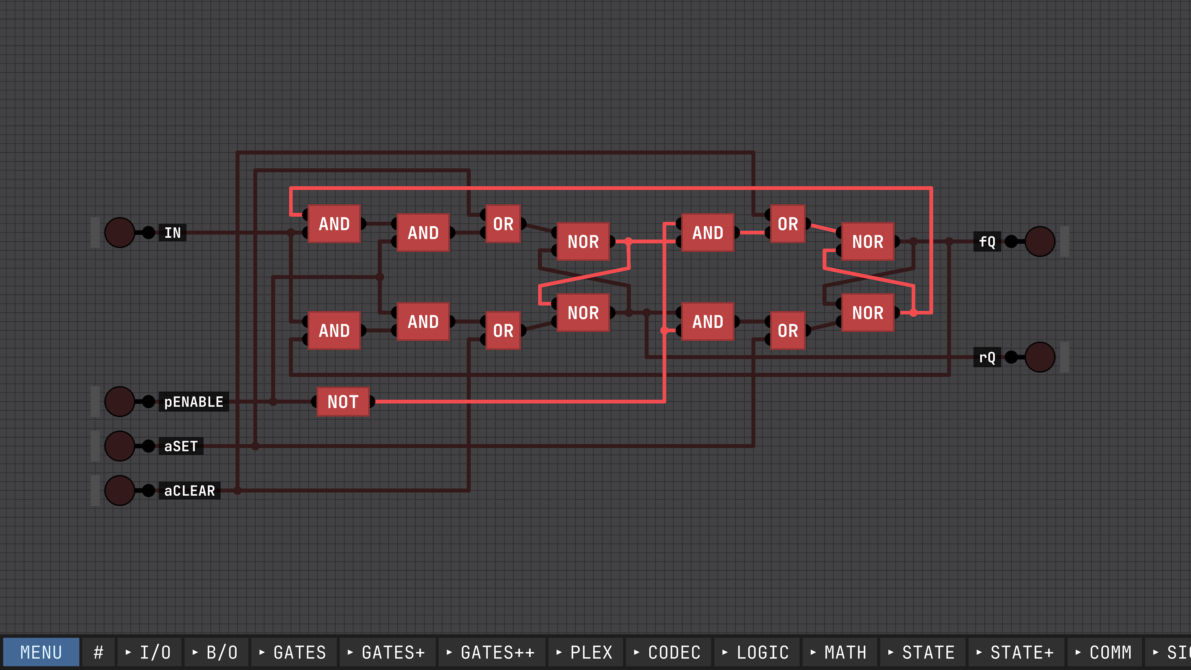
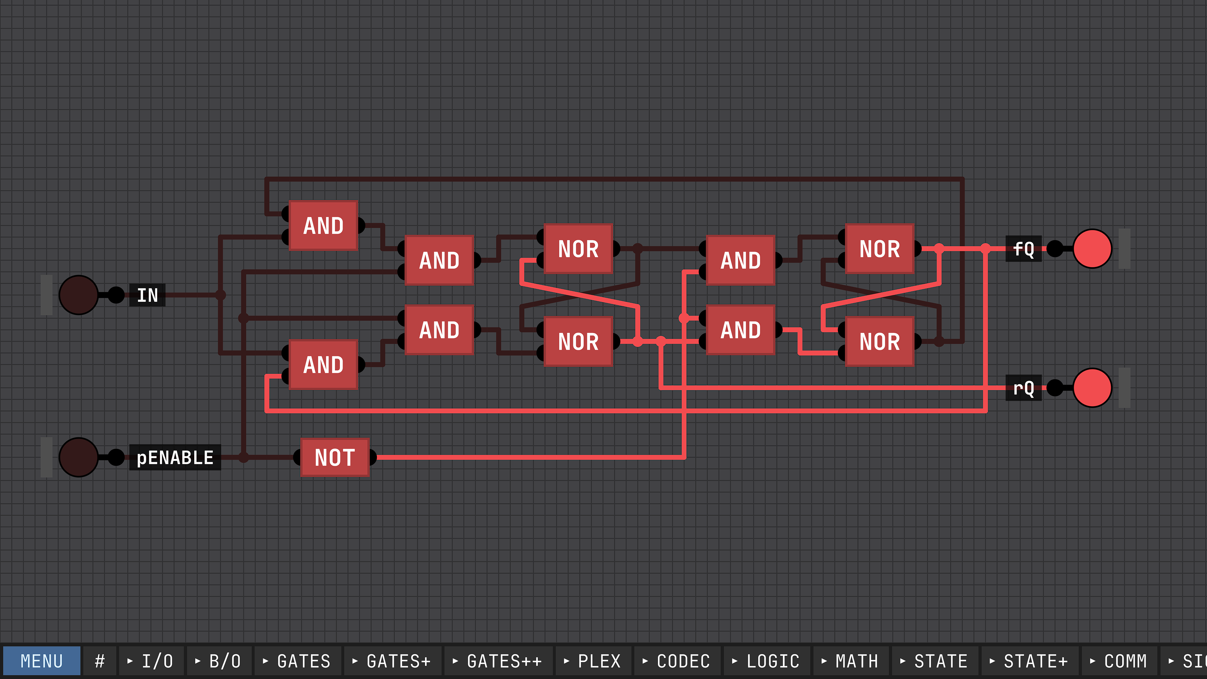
In real life, latches and flipflops start in an unknown state. In the simulation *some* style of latches and flip-flops (those built on cross-NOR and cross-NAND gates) also start in an unknown state. Within the simulation AND-NOT-OR style latches start in a known state. There's a bit more nuance to it, but that's the gist.
TBH, I think this is better and more flexible. before you could only have 256 discreet delays, the values of which you couldn't change. now you can have any number, and can be finely tuned. you can still achieve the end result as the original proposal by using multiple pulsers and a demux or something. (though, I question if you need 256 as opposed to like, eight)
gotta not take it personally when contributing to someone else's open source project and it doesn't end up exactly how you may have originally intended.
NOR and NAND style SR latches will always start in an unstable state, both in real-life and in the simulation. NOT-AND-OR style RS latches *can* start in a known state *if* you package it up into its own chip (there's a bit more nuance to this, and there are still some oddities, but they will start in a known state). This normally isn't true in real life, but in the simulation, it works out that way.
You can read up on my explorations of simulation oddities, and how they specifically apply to latches here: https://github.com/SebLague/Digital-Logic-Sim/issues/326 (there's a lot that I "learn" and then "unlearn" through that thread, so I would read it in its entirety)
Just so you know there is some known funkiness in the simulation with latches both SR-style and RS-style (or any feedback loop, really) and how their initial starting conditions (which are random) affect their future timing behavior. Sometimes it can take an extra tick to set, sometimes an extra tick to reset. Once the initial state is determined, it will be consistent, but there's no way to determine how it will act before the initial state settles.
Also (and there's some nuance to this that I'm going to skip over) RS latches that exist as their own component will always start Low, but an SR latch's will always start in an unknown state.
also if you use an RS-style latch, and have a NOT gate attached to the output to serve as the Q-compliment, there is a chance that you will have both the Q and the Q-compliment have the same value for one tick.