
Indie game storeFree gamesFun gamesHorror games
Game developmentAssetsComics
SalesBundles
Jobs
TagsGame Engines

Digital Logic Sim

​A minimalistic digital logic simulator · By Sebastian Lague

Disconnected state checker

A topic by jacka328 created Apr 30, 2025 Views: 174 Replies: 5
Viewing posts 1 to 3

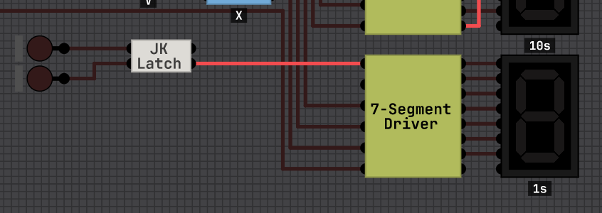
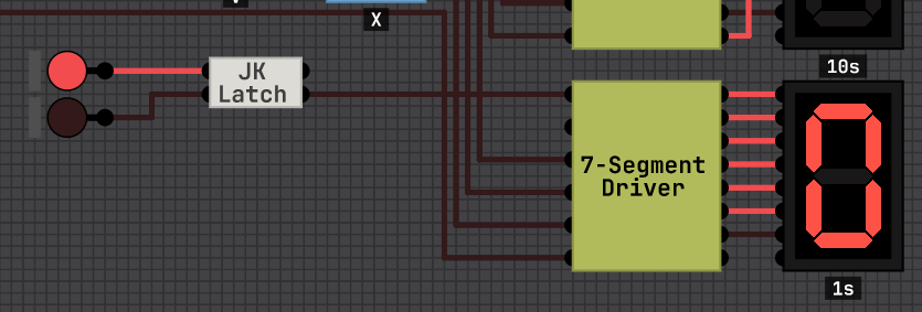
I was making my adder and subtractor and got side trackt by putting a number readout in them and then ended up revamping my 8-bit number display(I LOVE THIS GAME FOR THIS REASON)  but i wanted to add a function to the display where if nothing is pulgged in or its getting that disconnected state from the tri-state logic chip it goes completely blank where as now it shows a zero so im suggesting and asking that you add a disconnected state check chip or something i just would want something that lights up when its only disconnected not the zero or one state.


ALSO I LOVE YOU FOR RETURNING TO THE SIMULATION!!

(1 edit)

Something has to tell a tri-state buffer that wire should be disconnected. You can NOT that signal, and use that as a "isDisconnected" indicator.

see this discussion: https://github.com/SebLague/Digital-Logic-Sim/issues/428

so i guess why that wont work for what I'm doing is because I trying to have the chip read from a bus only so theirs a possibility of the bus not having any data on it in which case I would want to display to read nothing instead of zero that it currently reads as and I cant not the tri state buffer because that would be coming from a buss buffer somewhere else on the bus that the chip I'm making wont have access to 

(1 edit)

I imagine you're already using ripple blanking, so you can have the display off by default. Then use a single latch to turn the display on and off.

I also imagine your display has a register which already has a load and reset function. You can use those same lines to the display.

This way your computer has more deliberate control over the display. I just implemented this on my computer and it works great.

I believe in a real computer you couldn't have a "disconnected detector" as a disconnected line could have any errant signal on it since it is not tied to ground.

so in real life i think the equivlent would be a computer that runs 3.3 volts their 1 would be just 3.3 volts while their zero is actually just low not 0 so like 1 volt and so if it was real life all id want is something that's turned on by 1 volt but not 3.3 kinda like two capasitars right after another where 3.3 passes the first so it stops their but if it was 1 it could go through due to the 3.3 not stoping it where the relay is kinda acting like a repeater from Minecraft but then have a second repeater so that this one would have the 1.1 or 0 volt goes to the tongle pin where the 0 would leave the relay open allowing just a straight 3.3 from the power supply but if a 1.1 was given it would close the relay showing a zero zero also I know I'm kinda using relay backward in this example just think of an inverted one

(1 edit)

That's not actually how that works.

1 = 5v (or 3.3v in your example) and 0 = 0v (or 1v in your example) isn't quite true and is a big oversimplification. 

When a chip asserts a 1, it is actively connecting its output to VCC, and when a chip asserts a 0 it is actively connecting its output to GND.
When no value is asserted on a bus, its not that it *actively* has 0 volts on it, it is that nothing is putting a value on it - that's what they mean by it "floating" - it could have some voltage potential relative to ground because nothing is anchoring it to VCC or GND. but that voltage isn't being asserted - its noise - and that noise is indistinguishable from some value if a chip tries to read from it.

Because of that, you can't really use any logic gate to determine if something is asserting something onto the bus from the receiving end - that's what control signals are for.