
On Sale: GamesAssetsToolsTabletopComics
Indie game storeFree gamesFun gamesHorror games
Game developmentAssetsComics
SalesBundles
Jobs
TagsGame Engines

Zhatt

30
Posts
2
Topics
1
Following
A member registered Jul 06, 2019

Recent community posts

Hah, yes, sorry, 2023.

Like in real life, latches will settle randomly due to the the race condition.

If you mean the color, just right-click on the output.

Glad you figured it out. I posted about a similar issue here and there's on on-going discussion about the race condition issue here.

How does the inside your counter look?

Good chance your counter is skipping. It's a common issue in DLS right now. What 'steps per clock' are you running in the settings? Does it still do it if you increase the steps per clock and re-load the chip?

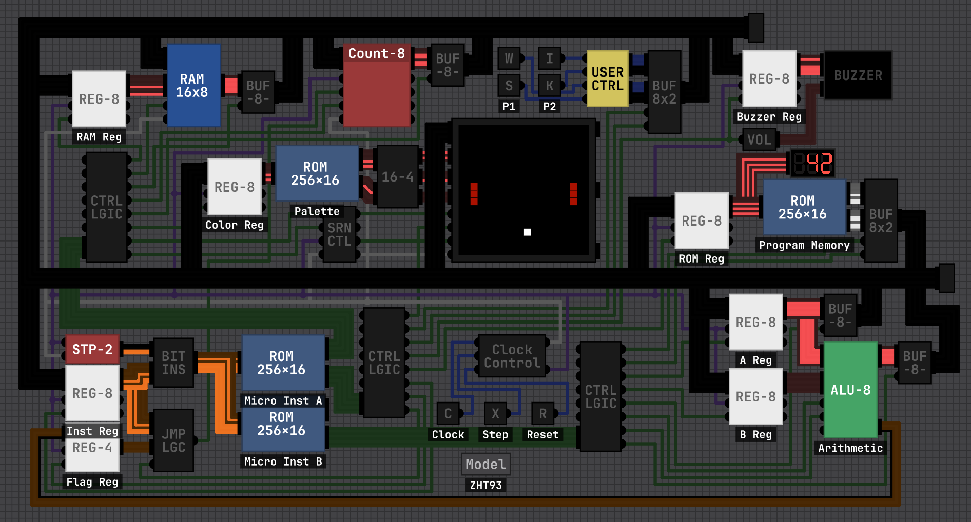
I did some minor simplification and wire management. The biggest change is I removed the clock from the registers making them asynchronous. Their load signal is robust enough for the task and this means less wires and logic. I left the clock on the RAM, but it could probably be easily removed as well for more efficiency. 

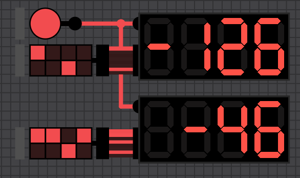
I moved the number display to the program memory as it more accurately displays the line of code being processed. As the double-dabble and 7-segment drivers in the display are relatively complex, you can speed up the simulation by removing that component. I left it in for ease of de-bugging code.

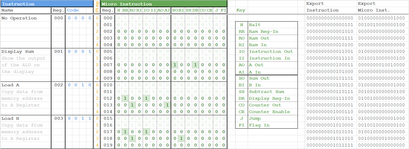
The previous code and compiler works for this version, though I did update the micro-instructions B ROM to have the high and low outputs mirrored so either could be hooked up.

(1 edit)

That video is from 2023 and is using an older version of DLS. The disappearing wires are likely a bug that has been fixed since.

(1 edit)

I've been working on this one for a while now. PONG!

I have more details in this thread: https://itch.io/t/4920753/pong-8-bit-computer

Seb, if you want to use any part of this for your program or videos, go ahead.

(3 edits)

I have been working on this one for a while now, but I have managed to get fully-featured pong running on my 8-bit computer (ZHT-92).

Check out the video:

The game features:

  • Bouncing ball with sound
  • Two player paddles that stop at the screen edge
  • A separate goal zone for each player
  • Recording scores with 'pips' on the bottom of the screen
  • After a goal the game waits for player input before continuing
  • After three goals, a 'win' screen is displayed with the player's number.

It took me about three or four weeks to build the computer and program pong into it. You can see the my older versions here.

For the best efficiency in Digital Logic Sim, I have used as few logic gates as possible other than the basic NAND gate. Most chips are only one level deep. The JK Flip-Flops must be their own separate chip, or else there are stability issues and the counters get stuck. It is running at about 10,000 steps per second with 2 steps per clock cycle (~5kHz). Each instruction is broken into four micro-instructions, so it is running at about 1200 lines of code per second in the video (although it can be unstable at this speed, and I usually run it at 3 steps per clock.)

Pong completely fills up the program memory at 256 lines of code. 72 of that is just to the draw the 'win' screens. The main loop is about 137 lines.

I'm not sure if I want to get snake running on this next, or start a new project. If you do anything with this system, post it here!

Right click on the pulse chip and you can change the setting.

I don't know what you're trying to say. You can set the pulse chip to whatever you want, including one tick.

Yes, I started making a 16 bit system but realized it's not necessary. It would just make things more complicated for the level of code I want to run.

Thanks! I've emailed you the project files directly. I'd like to add a few more features and clean it up before I release it publicly.

Like this. The pulse blocks the output for the time you set. You can also put another pulse chip on the top line if your input is shorter than your delay.

(1 edit)

I have given my computer a rework and am coaxing it to play pong. Check out the video:

The major elements done, but I'd like to add some flair to it, such some sort of graphic shown when you score, and score keeping. The issue is I'm running on the edge of speed for what is playable. Adding too much more will make it too slow.

Once I've added a few more features and cleaned up the wiring, I'll give a proper video tour.

This is useful info, thanks. Another shortcut I stumbled across:

  • Ctrl+R to center the screen on the chip

It might be useful to eventually add all this info in the 'About' section on the main menu.

(1 edit)

I built mine following Ben Eater's tutorials:
https://www.youtube.com/playlist?list=PLowKtXNTBypGqImE405J2565dvjafglHU

Start at video #24, the JK Flip Flop.

I second the sentiment. This program really scratches a particular itch, and is one of the most addictive "games" I've played. Thanks for sharing this program with us.

Dude, that's really cool. And smart implementation too.

I assume that can do more complex math, like multiplication and division?

Neat!

Think of it this way: the least significant bit goes at the bottom.

Here's my basic 8-bit computer where I'm trying to keep elements as exposed as possible while also still keeping it tidy. More info in this thread.

Here's a video of my computer. It's calculating the Fibonacci sequence, and once it overflows the numbers turn red and the program restarts. It is running quite efficiently. This is partly due to minimal nesting of chips, but I also trimmed the microinstructions down to 4 instead of 5. The clock-synchronized flip-flops in the counters means it rarely runs into errors.

I skipped adding RAM to the system mostly to make programming it easier, but you could easily replace the memory ROM with RAM. I also didn't add a flag registry and just fed the carry bit directly into the instruction register.

Here are the project files and operations if you want to experiment with it. (I just realized that in the video the steps are counting to 5, but I've fixed that in the files)

After making this system, I'm really starting to bump into the limitations of an 8-bit system, such as 4-bit address allowing for only 16 memory locations. I'm tempted to make a 16 bit system next.

(2 edits)

Question: how do you access the RAM? I see you've use the top bit of the address to toggle between ROM and RAM, but can you input that bit in the code?

If the instruction takes the top four bits, then the address can only be the bottom four. That makes only 16 memory locations total.

I'm running into the same issue on my system and I'm considering adding control line to select either RAM or ROM. (though it would still be limited to 16 locations each).

The frequent fixes are nice. Thank you.

(1 edit)

I imagine you're already using ripple blanking, so you can have the display off by default. Then use a single latch to turn the display on and off.

I also imagine your display has a register which already has a load and reset function. You can use those same lines to the display.

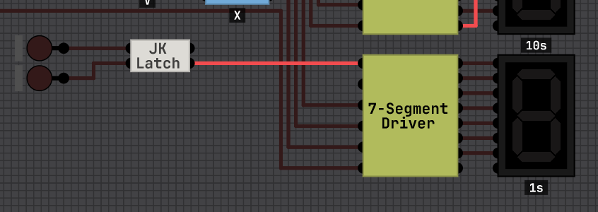
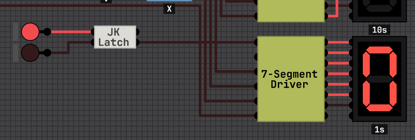
This way your computer has more deliberate control over the display. I just implemented this on my computer and it works great.

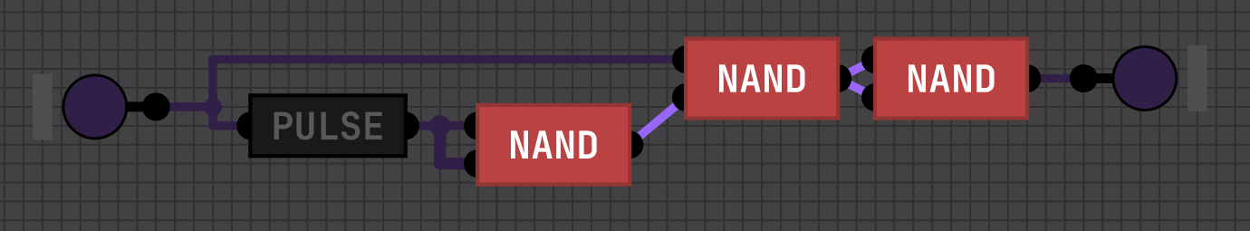
I believe in a real computer you couldn't have a "disconnected detector" as a disconnected line could have any errant signal on it since it is not tied to ground.

I just use another 7-segment display. This way it looks consistent if you implement ripple blanking with the sign.

(1 edit)

The "ZHT80" is my project computer I've been building as I follow along Sebastian's and Ben's video series. So far it is essentially the same as Ben's 8-bit breadboard computer, but with my own solution for instruction memory and lookup.

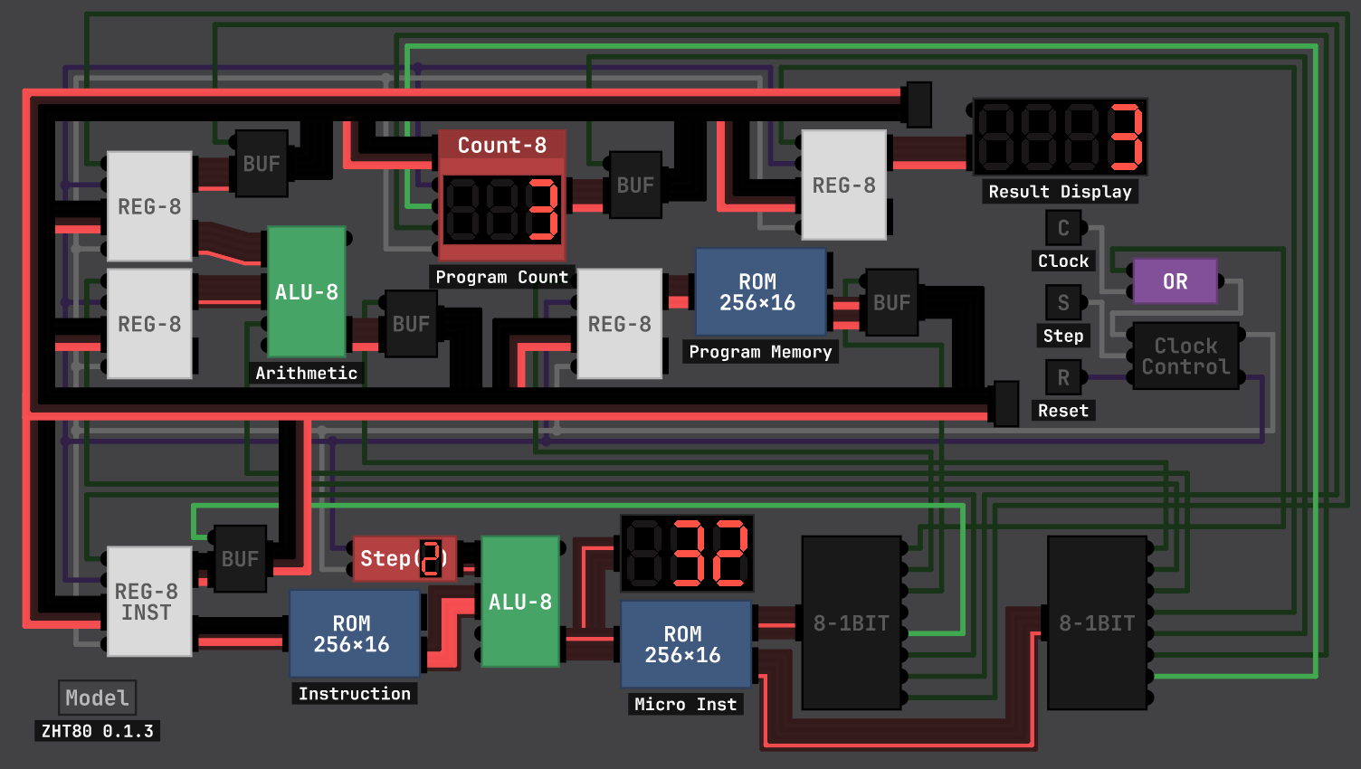
I'm trying to keep the design as clear and understandable as possible while still keeping it compact. I'm also minimizing the number of nested layers inside chips so its easy to see what is going on internally.

As I'm not a programmer, I built a instruction compiler in Google Sheets. I can set the micro instructions then copy the export column into the micro instruction ROM. I'm still figuring out how I can add flag bits to this spreadsheet without making it overly complicated. Once I set up more instructions I'll create a program compiler in another tab.


Things I still plan to add:

  • Flag register and flag instructions (Turing complete)
  • Instruction compiler spreadsheet
  • Error message on display
  • Keypad for manual entry
  • Signed integers (the display has a toggle, but it's not connected)
  • Dot display

I'm considering reducing the micro steps from 5 to 4. That would make processing quicker and give me room for more instructions, but would require adding explicit instructions for moving data between registers. I'm not sure which would be more efficient ultimately.

Once I add flags and ram, I'll record a video for Seb's playlist. I can also share the spreadsheet and project files.