
I've added this to the description now. Note that this information is also available in the font files themselves, though it's not in the license section of the TTF at the moment, I'll try to fix that in a later version.
A member registered Mar 27, 2016 · View creator page →
Creator of

A proportional serif pixel font aiming for wide coverage of Latin scripts in Unicode

Play in browser

Play in browser

Play in browser

Play in browser


A game made for the Weekly Game Jam #40, with the theme 'Small World' !
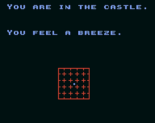
Puzzle
Play in browser


Recent community posts
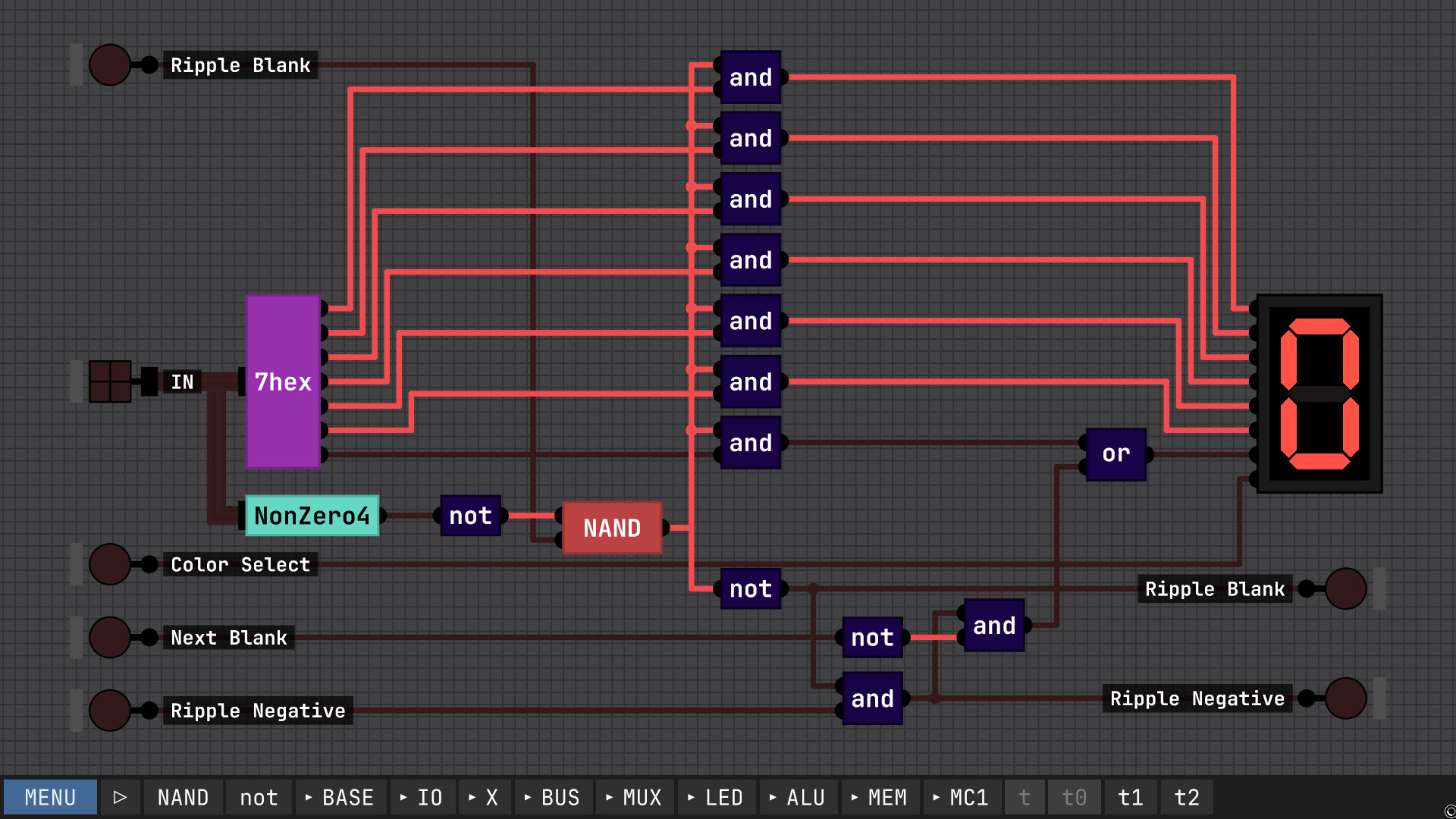
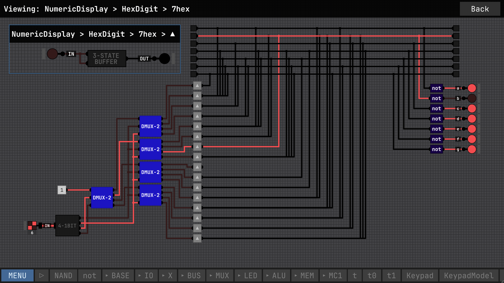
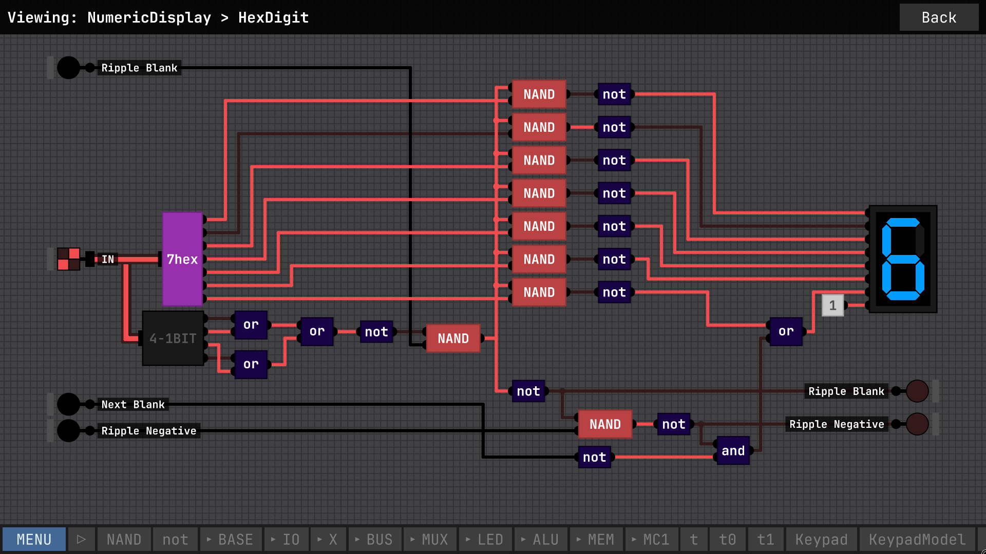
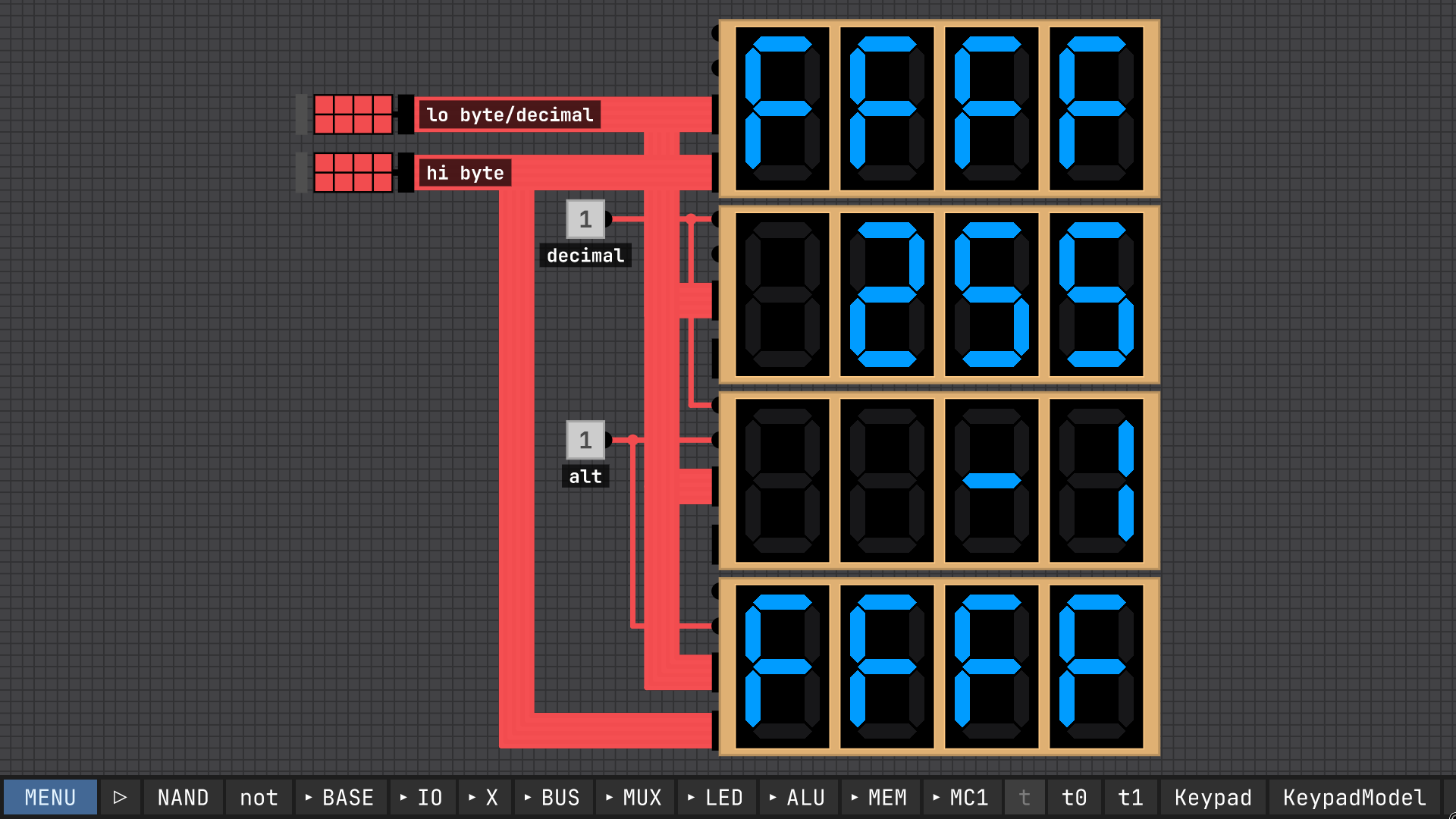
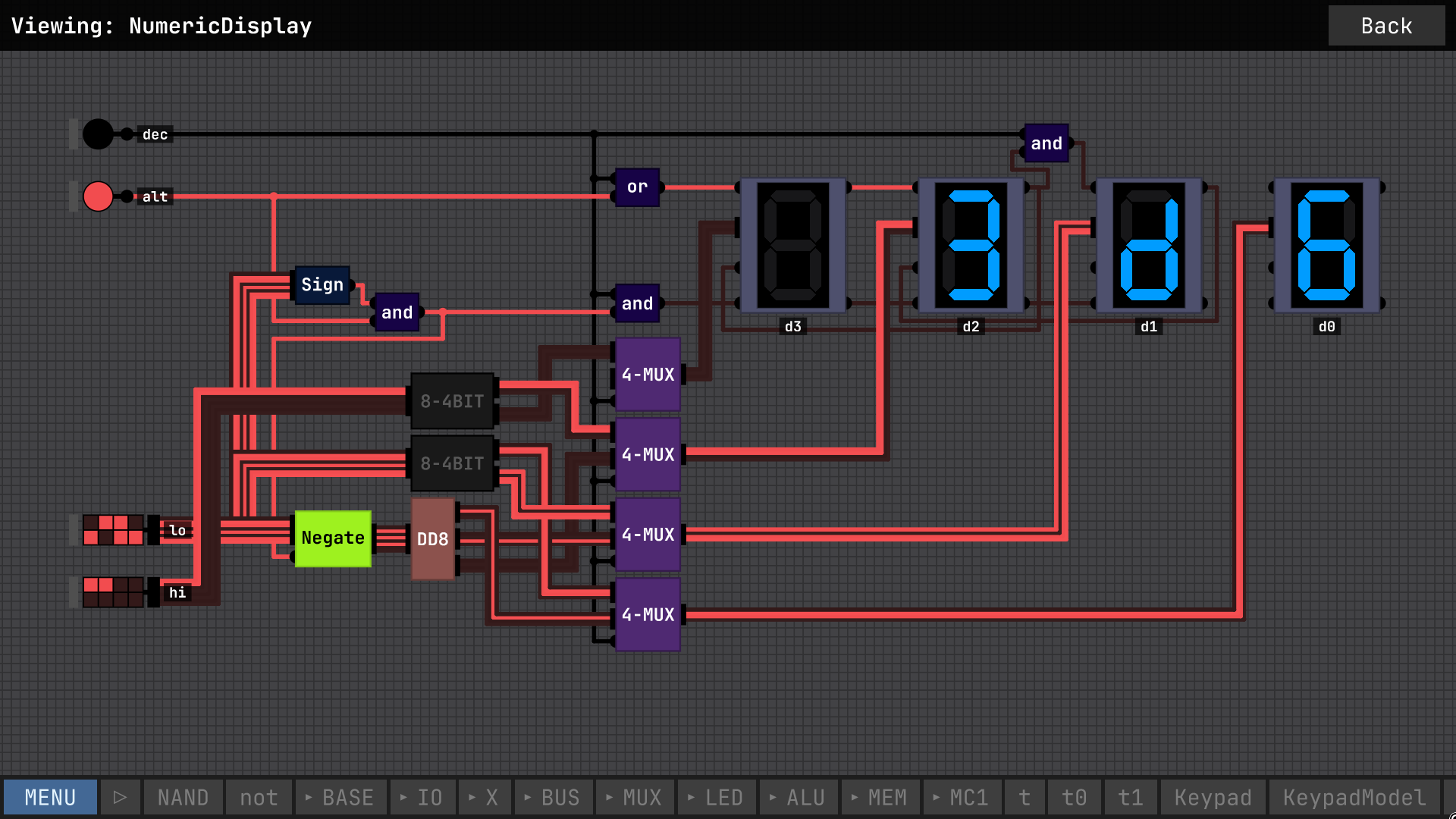
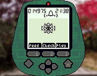
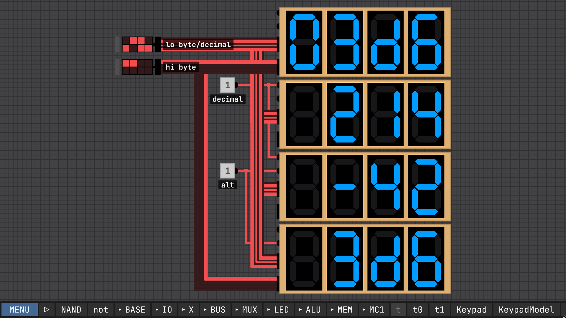
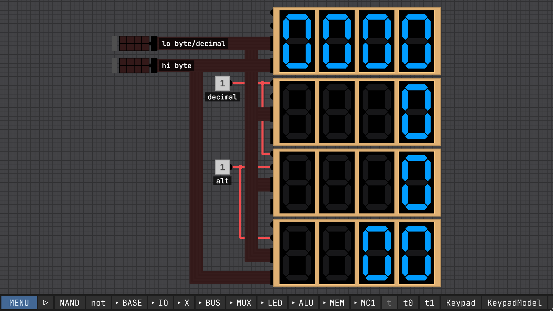
I created this numeric display following along with the videos and tweaking things, along with developing my own design for a bus-based seven-segment encoder. It has four modes: (top to bottom in the screenshots) four-digit hexadecimal, unsigned decimal, signed decimal, and the last mode being hexadecimal with zero blanking for the first 2 digits, so it will display a single byte padded with a leading zero, but display the upper byte with blanking. Note that all multi-bit inputs are LSB at the top, in other words little-endian in reading order, the opposite of the convention used in the videos the numeric display built in to IO pins.
I'll throw my implementation in the ring, too. Just a pair of D latches in series, looped back to a mux, much like in the videos, to make a "register". Then tie the inverted output back around to the input, optionally through a reset, and pulsing the clock while "store/enable" is high will toggle the output.
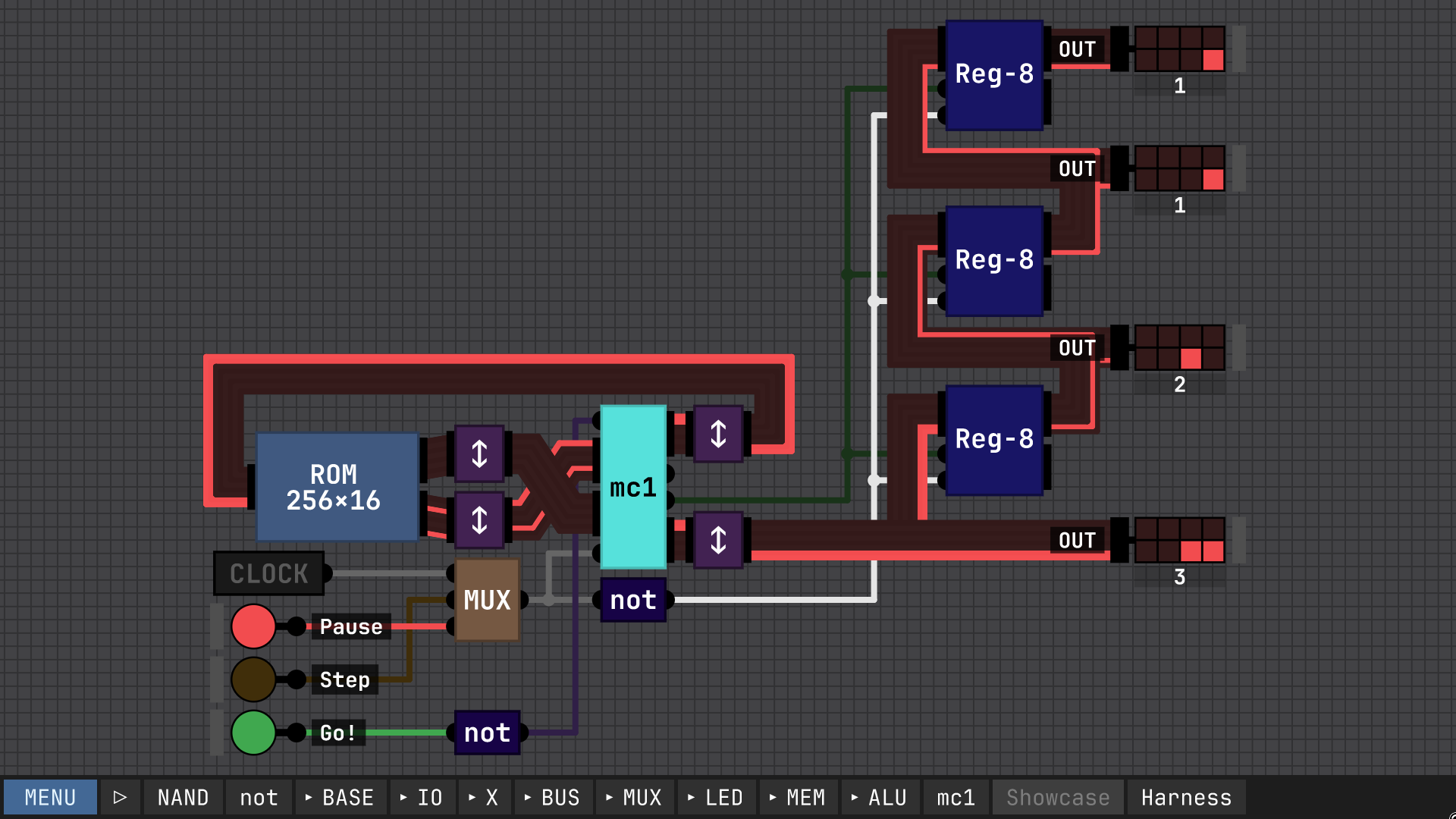
Here it is hooked up to a ROM with a program to generate Fibonacci numbers on it, along with a simple output queue. One notable thing about this design, I designed all the chips with the least-significant-bit at the *top*, so everything has to be swizzled about to work with the built-in ROM and output display. I didn't realize this would be a problem until I was about halfway done.
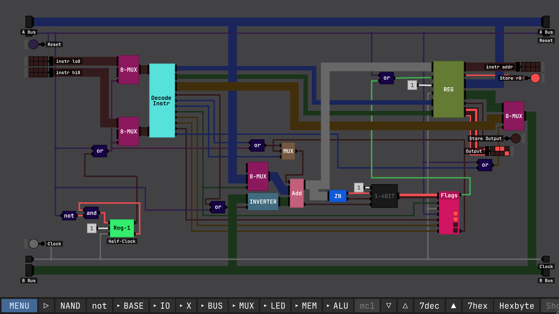
Digital Logic Sim community · Created a new topic Finished a recreation of my simple "MC1" CPU architecture
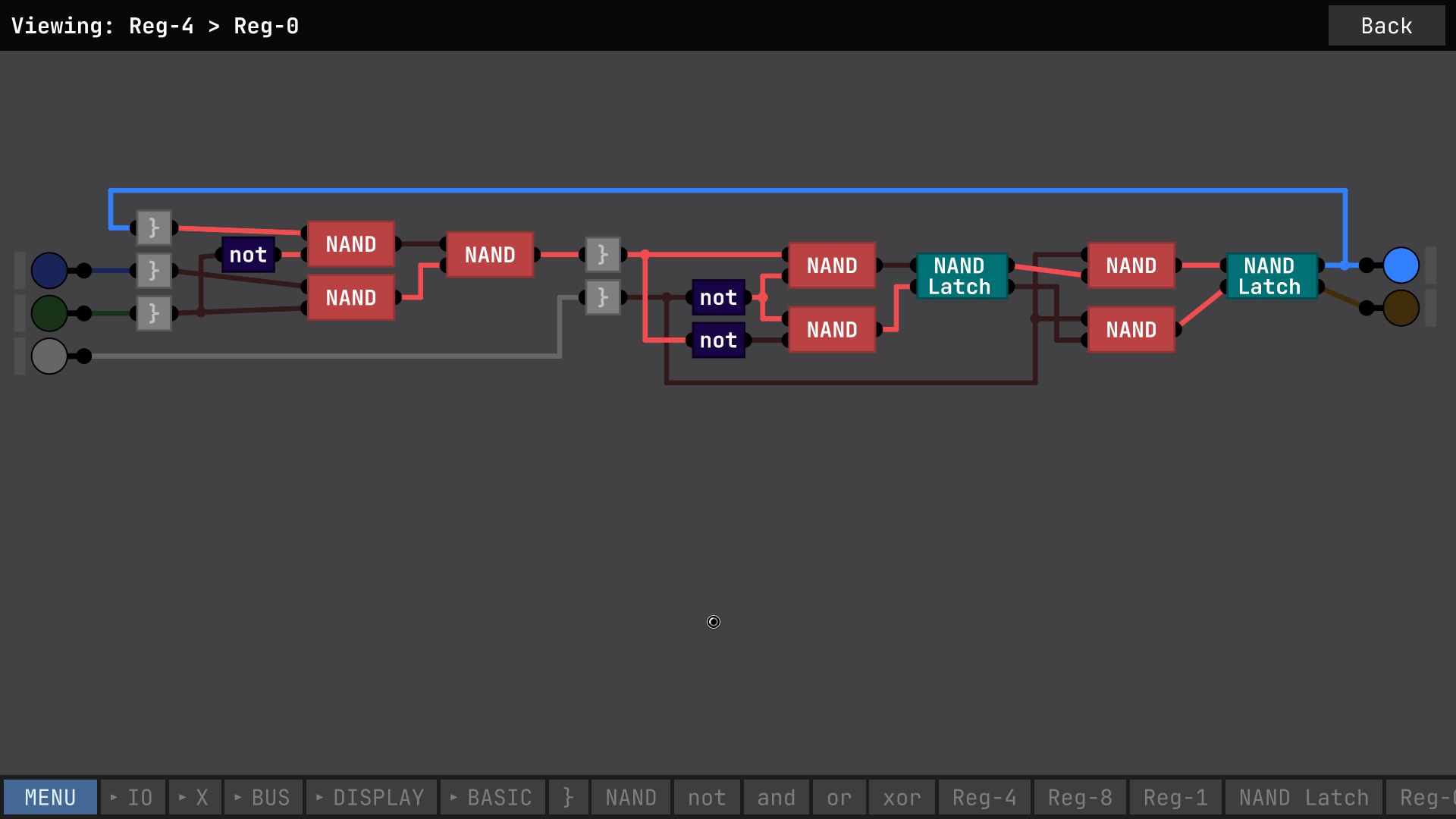
Please excuse my sloppy wiring. I have highlighted in Violet here the offending signal, which flickers in only some instances of this chip.
I don't really understand why this flickering signal is happening. My understanding is that the NAND SR latch should only have a race condition if both the inputs are *high*. Is there some obvious thing I'm doing wrong or some way to fix this? Note that the gray bracket chips just pass the data through, they're just an easy way to re-connect multiple things at once.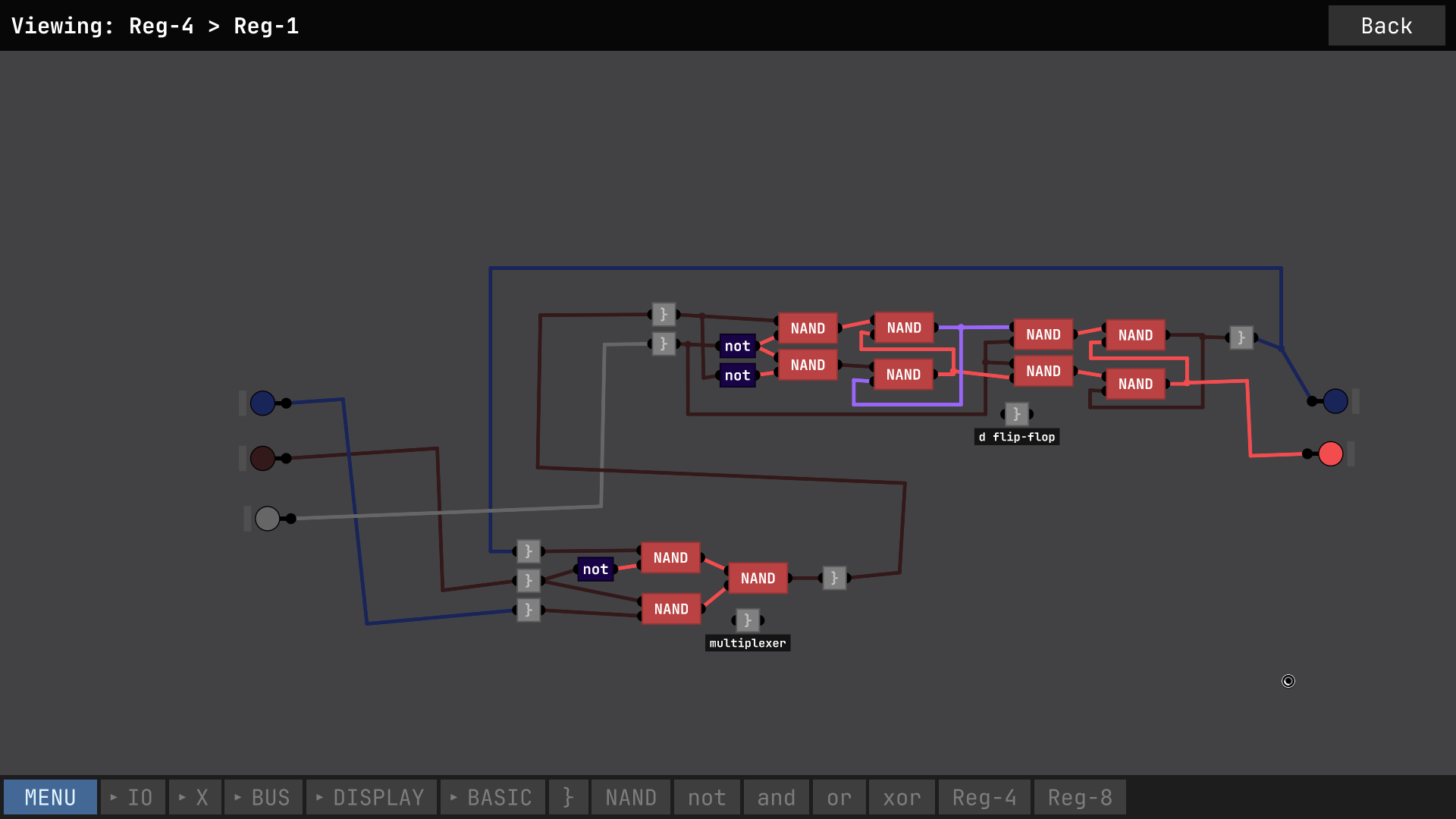
It was annoying after the first round when it turned out all my work was for nothing as I didn't know I'd lose so many points for stuff being outside the lines when it should be inside and vice-versa. Also kinda annoying that it doesn't offer to save or screenshot or anything and just deletes your island when you click again on anything after it's done.
I admit that the first complaint is sort of my own fault for skipping the rules, but I think the reason I skipped the rules is because it was a lot of text all at once. I like that the cards each tell you how they work, that's much better than a big wall of text up front that you have no idea how to parse yet because you don't actually know anything about how the game works. I think it would work much better if you didn't show the individual tile's info at the start and just showed the other info, like the explanation of what "near" means. And also, during the border-drawing mode, show the info about which features/tiles should be inside, and which should be outside the lines.
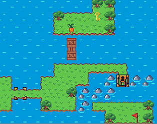
Also, here's my second try at an island.
