
Indie game storeFree gamesFun gamesHorror games
Game developmentAssetsComics
SalesBundles
Jobs
TagsGame Engines

Digital Logic Sim

​A minimalistic digital logic simulator · By Sebastian Lague

Finished a recreation of my simple "MC1" CPU architecture

A topic by gardrek created Apr 22, 2025 Views: 263 Replies: 6
Viewing posts 1 to 6

If there is any interest I'll upload the project file and explain how to program it. After I straighten out all the wires inside every chip, lol

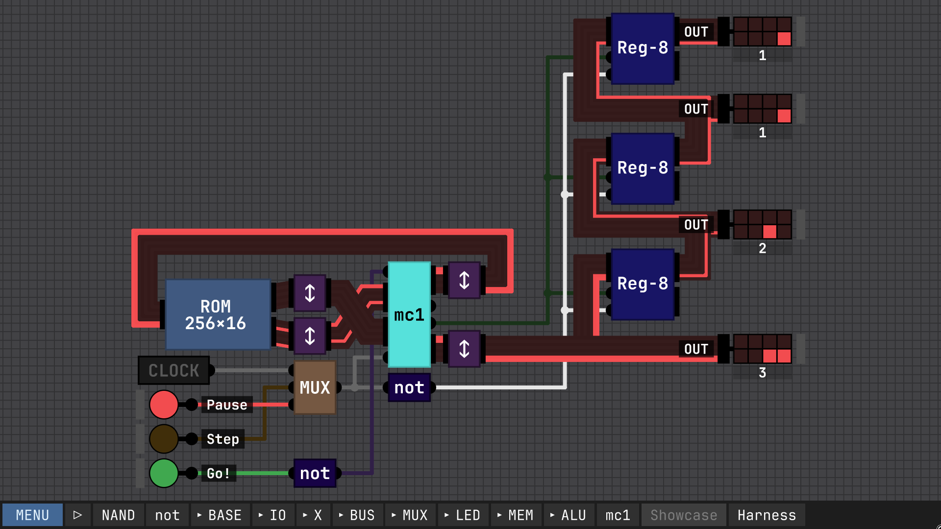
Here it is hooked up to a ROM with a program to generate Fibonacci numbers on it, along with a simple output queue. One notable thing about this design, I designed all the chips with the least-significant-bit at the *top*, so everything has to be swizzled about to work with the built-in ROM and output display. I didn't realize this would be a problem until I was about halfway done.

(1 edit)

I would share the project file but first I have to figure out where it stores things on Linux lol
EDIT: ah yes it's made in Unity, so you can find it in ~/.config/unity3d/
pressing ctrl+shift+alt+O on the main menu also will open the location in your file browser

Developer

Looks great! I'd definitely like to check it if you share the files. Would also love to add it to the community playlist if you're up for recording a short video of it in action :)

I'll look into making a video later, but for now here's a download link, and a bit of a programming cheat sheet.

https://cdn.discordapp.com/attachments/979914100068974672/1364165157374394368/mc...


[overview]

The MC1 architecture is fairly simple, consisting mainly of a simple ALU, a bank of 16 8-bit registers, and a read-only connection to an external ROM or RAM for reading in instructions, and a clock input. Each instruction takes two clock cycles to complete, writing on the rising edge. While most of the registers are general-purpose, the r0 register is the program counter. Note that to effect a jump to address N, one must write N-1 to r0, which is then incremented. Additionally, r15 is used as output.


[control word bits]

NOTE: this layout is implementation-dependent. this document describes the layout in the implementation for Sebastian Lague's Digital Logic Simulation program

there are two control word layouts, depending on if the high bit is set or not:

15 .. .. ...11 .. .. 08
07 .. .. 0403 .. .. 00
=0 cN c1 c0AL Cs Cf bN
b3 b2 b1 b0a3 a2 a1 a0
=1 cN c1 c0d7 d6 d5 d4d3 d2 d1 d0a3 a2 a1 a0

For each instruction, the contents of the A bus is added to the contents of the B bus and sent to the Q bus, which is conditionally written to the A register.

When writing to the flags register, if the result of the addition is zero, negative, or there was a carry, the appropriate flags are written.

The four flags selected by Condition Select are: 0b00=Always(A), 0b01=Zero(Z), 0b10=Negative(N), 0b11=Carry(C).

The ALU performs essentially one operation: add with carry. But by controlling the carry input and inverting B, you can also perform subtraction.

If "ALU Op" is low, then the A bus is pulled low, effecting a transfer/move from register A to B. However, you can still use the carry flag and invert B controls, giving access to an invert command and an increment / decrement command, using a zero register (NOTE: on some platforms, reading r0 to the B bus results in a read of 0).

a0-a3   A Select            Selects the register to be the A argument of the operation.

b0-b3   B Select            Selects the register to be the B argument of the operation.

d0-d7   Immediate Data      Immediate data sent to the B bus instead of selecting a B register.

bN      Invert B            The B bus contents are bitwise inverted before entering the ALU.

AL      ALU Op              Output the chosen A register onto the A bus, and write the flags register.

Cf      Force Carry         Carry in to the ALU is pulled high. NOTE: Setting both Force Carry and Carry Select high is implementation-dependent.

Cs      Carry Select        The carry flag is sent to carry in. NOTE: Setting both Force Carry and Carry Select high is implementation-dependent.

c0-c1   Condition Select    Selects a flag, and only writes to the A register if that flag is true. If ALU Op is high, flags are always written.

cN      Invert Condition    If this bit is high, the condition is inverted, so the write to the A register occurs only if the flag is low.


[example instructions]

0x0023 = 0b_0000_0000_0010_0011 = MOV r2 -> r3

0x0823 = 0b_0000_1000_0010_0011 = ADD r3 + r2 -> r3

0x0c23 = 0b_0000_1100_0010_0011 = ADD r3 + r2 + Carry -> r3

0x0b23 = 0b_0000_1011_0010_0011 = SUB r3 - r2 -> r3

0x0223 = 0b_0000_0010_0010_0011 = INC r2 + 1 -> r3

0x8ff3 = 0b_1000_1111_1111_0011 = IMM #0xff -> r3

0x8ff0 = 0b_1000_1111_1111_0011 = JMP #0xff

0x9ab0 = 0b_1001_1010_1011_0000 = JMP #0xab if Carry

how far can you push your clock speed?

ngl I didn't tune the clock at all, the settings in the project file are all i tried (i think 10 steps per clock and 60 per second)