
Thanks Charlie, I should have also asked are there going to be updates, I know we talked about inlays and was wondering if that is still moving forward.
Joe..
Charlie....
I tried a 10.5 deg inlay. While the male fit in I couldn't seat it deep enough, think I have to offset one of the other to make it fit. All the missing pieces are because I didn't let the glue dry. I knew it wasn't seated correctly so I rushed ahead. That's not much of an angle needs some tweaking but it does work...no wonder I couldn't duplicate that color...Joe
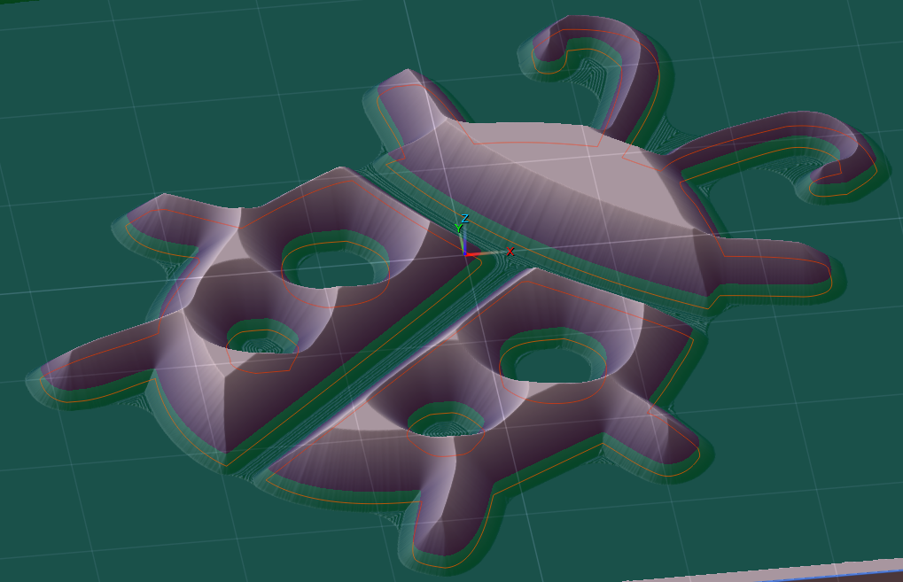
 Charlie....
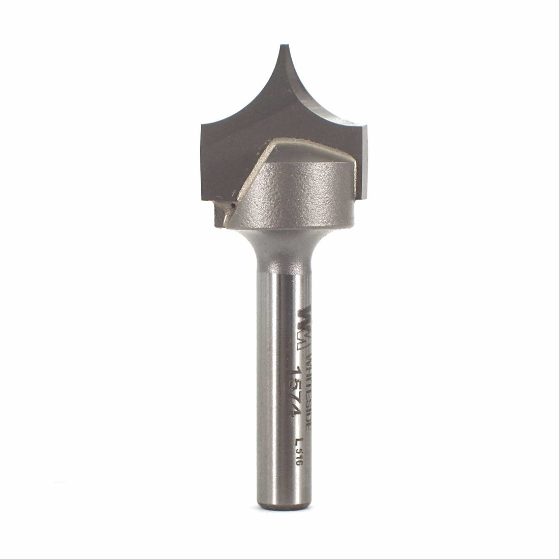
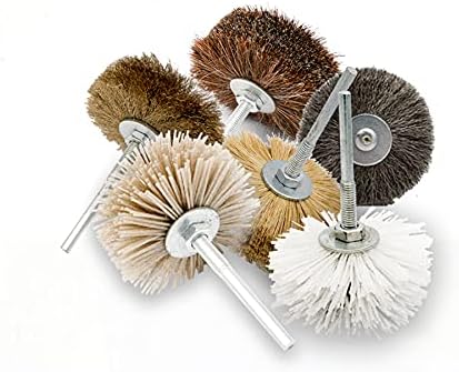 A bit off topic.... I've been using these for awhile , been great for sanding after cutting. Come in different grits they work well. Alligator looks great.