Indie game storeFree gamesFun gamesHorror games
Game developmentAssetsComics
SalesBundles
Jobs
Tags

Deftware

322
Posts
10
Topics
59
Followers
10
Following
A member registered May 30, 2015 · View creator page →

Creator of

Recent community posts

Hi Joe,

You can define your tools, add them to the tool library, and then re-arrange them so the ones you most commonly use occupy the first ten tool library slots. Then, when you're working on a new project, you can just click 'Load Library to List" while in the Project Tools mode, which will copy the first ten tool definitions from your tool library to the current project automatically.

For the project size and origin all that matters is that you define a canvas volume that fits the cutpaths you want to generate - it doesn't have to be the same size as your workpiece but some people like to treat the canvas volume and its dimensions as their workpiece. The machine origin is relative to this volume - which is to say that wherever you want to zero your machine, relative to the generated toolpaths, is restricted to the canvas volume and its extents.

Does this answer your question?

 - Charlie

No problem! Glad to help :)

 - Charlie

(1 edit)

Hi Joe,

With the Parallel Carving operation you can set the 'Cut Angle' parameter to 90 degrees to make the cuts go along the Y-axis.

Hope that helps :)

 - Charlie

(1 edit)

No problem! Glad to help :)

(1 edit)

Hi oslow1,

You can use the Min Depth parameter to prevent cutpaths from cutting everything above the depth value you set. i.e. for a 0.5" thick canvas if you set Min Depth to 0.25" then cutpaths will be restricted to the bottom half of the canvas volume, like this:


Hope that helps!

 - Charlie

Hi Joe,

The only thing you can do is re-create the project next to itself on the same canvas. Firing up two instances of PixelCNC will probably be the easier way to go, with the original older project in one window and the new modified one in the other.

Hit the PrintScreen button on your keyboard and you should have everything copied to the clipboard to paste into an image editor program! ;)

 - Charlie

Reminds me of "cultured marble", which I thought was a funny way to try and hide the fact that it's just plastic :P

So no ballnose on the V-bits, you're just using a relatively small stepover? Is there any kind of manual cleanup after cutting - sanding or anything? They look really good, and detailed!

- Charlie

Looks awesome Doug! Good work :)

I'd never heard of Corian before, how's it cut?

Embarrassing regressions are a fact of life as an indie dev. Keep up the good work!

Hi Doug,

The best way to use the Trace to Paths function on an individual layer is to hide everything else first and just have the layer by itself. The green/red Z-contouring plane that the function shows is only really true and accurate when tracing the canvas to paths as a whole. When tracing individual layers it can be a bit deceptive because it doesn't take into consideration how the layer is being composited with the canvas, per its blend mode, and the tracing plane may not accurately depict what will actually be traced.

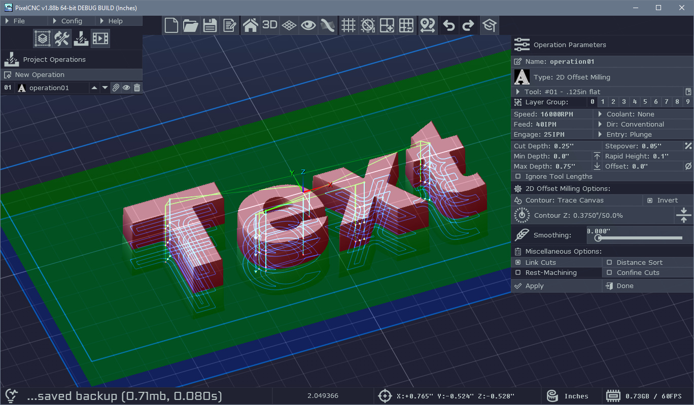
To make a text-layer that subtracts a certain depth you only need to make it's height the depth you want it to be and then move it up beneath the top of the canvas by the same depth. i.e. for 0.1" deep text you would make your text-layer's Z size 0.1", and if your canvas' Z size is 0.5" inches then you would set your text-layer's Z origin to 0.4". Then set the text-layer's blend mode to subtractive. This applies regardless of what is below the text-layer and how high it is. So, each 'step' in your project would basically have the same layer Z origin and Z size with only different text and XY position. 

If the text-layers are subtractively blended with the canvas, and they are the only things in a group (with the canvas' Z-fill set to the bottom of the canvas) then you will not see anything when that layer group is active. In order for the text to show it will need a different blend mode, or the canvas Z-fill to be set to the top of the canvas (not the layer's Z-fill as shown on the layer's properties, but the Z-fill under Canvas Properties).

If you want the text to blend the way you were originally trying you can invert the text-layer and set its Z-fill to the top of the canvas, and set its blend mode to Minimum. This will allow you to set the Z origin of the text-layer to the exact Z coordinate you want the text to be cut down to. The top of the layer (i.e. Z origin + Z size) will need to be at least as high as the surrounding material the text will be cut into.

I think you should be able to get the text Trace to Paths to work and then can use the medial-axis carving operation using a Depth Offset down to the material depth you want to cut into. There's no way to directly convert text or anything else into single paths to use with the paths-carving operation, unfortunately. The closest thing would be a function that calculates a medial-axis path but that will leave all sorts of extraneous paths on there at corners and stuff. It won't directly generate 3 lines for the letter 'H', for instance.

If you switch your text-layers to use the minimum blend like I mentioned above, you should be able to toolpath Group 2 if it only contains text-layers that are set up that way, but you will still need to set your Canvas Properties' Z-fill to the top of the canvas first, then you will be left with the text as pockets that you can generate toolpaths from.

I will do up an example project you can look at and email it back to you later today :)

 - Charlie

Sounds good! Look out for it in the next update, v1.70b, which should be out in the next month or two :)

 - Charlie

Hi Doug,

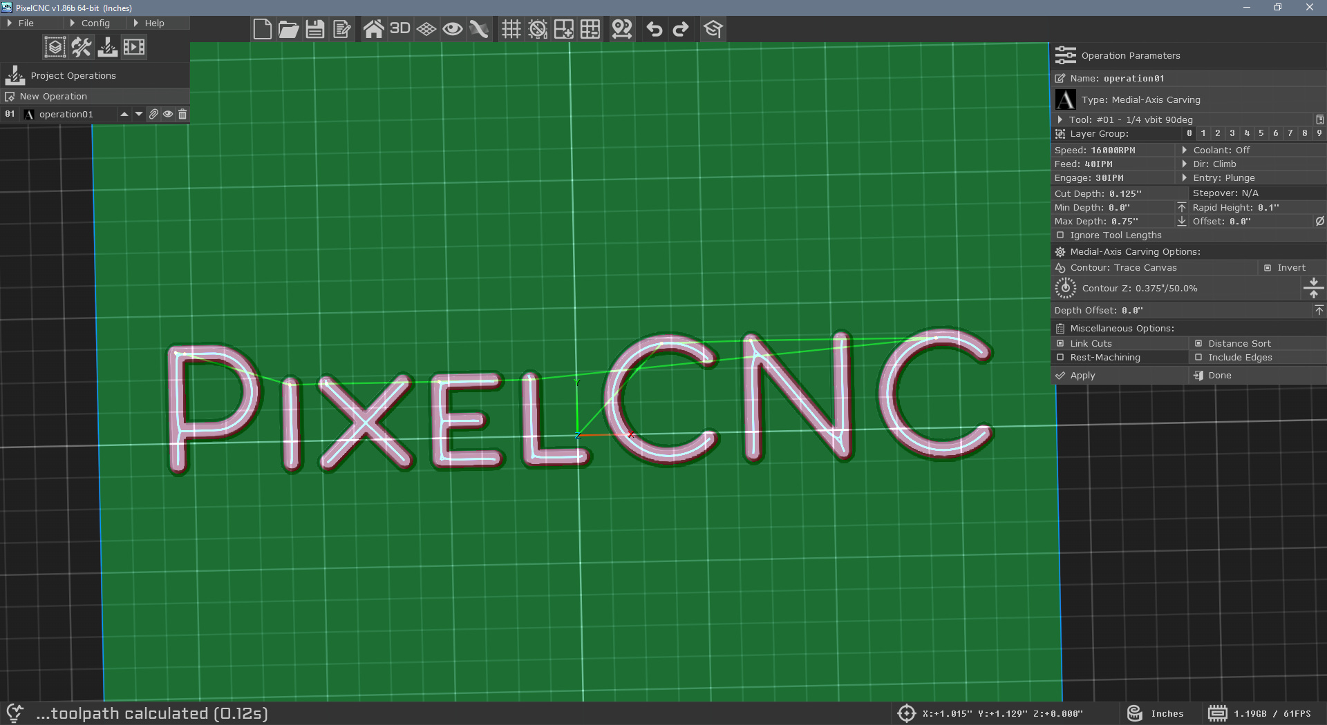
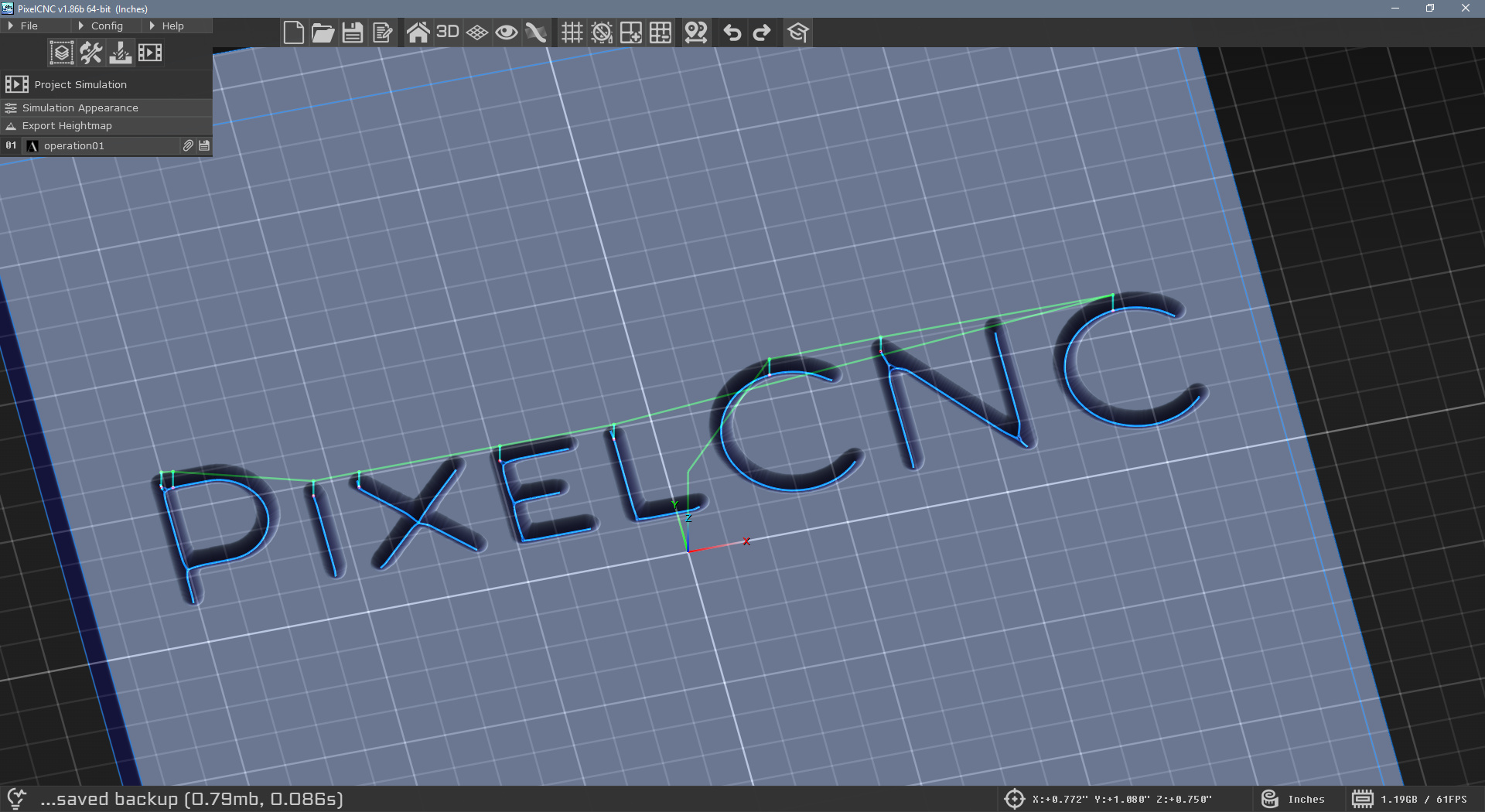
You can offset lower where the medial-axis carving operation will cut with the Depth Offset parameter that shows under the Medial-Axis Carving Operations toward the bottom of the operation parameters. A positive value will offset downward, where zero represents the top of the canvas, so you might have to calculate what offset to use. When your mouse is in the 3D view you can put the cursor on the point of the canvas you want to get the Z coordinate of by looking at the coordinate readout on the status bar at the bottom of the PixelCNC window. Just subtract that value from whatever the Z coordinate is for the top-plane of the canvas. If your machine origin is set to the top of your canvas then you just use that number, except flipped positive (because all coordinates on the canvas surface, with the origin set to the top-plane of the canvas, will be less than zero). That will put your medial-axis carving cutpaths where you want them! Rapids will stay at the Rapid Height above the top of the canvas though, regardless of your Depth Offset.

Just as an FYI you can also composite your text onto your canvas subtractively to get a better visual representation of what you're trying to do. For actually generating cutpaths I would do like you already are and trace the text to paths to use as contour input for the operation, or just have the layer groups with each text-layer inverted and Z-Fill set to the top of the canvas, which seems a bit more roundabout though but it will do the same thing.

 - Charlie

Hi Doug! :)

Yes paths-layers are always visible as layer groups do not apply to them. Groups can be thought of as separate canvases that are sharing the same pool of layers.

I was just thinking this morning about maybe having paths-layers also be a part of the layer groups though. Do you think that would be better?

 - Charlie

Just keep in mind that all editing functions are limited to the resolution that you set for your project's canvas, in pixels/inch, or pixels/mm - depending on whether you're working with inches or millimeters for your projects. You can set what measure units to create projects with via the Config menu, under CNC/CAM Settings.

Increasing the canvas resolution will allow for finer details to be represented and toolpathed, but it will make everything slower - so you only want to use the absolute lowest possible resolution without sacrificing the level of detail or level of precision your project needs. A larger project like a sign can typically get away with a lower resolution ~100-150 pixels/inch, while a small engraving probably would need 300-400 pixels/inch.

 - Charlie

Hi TedHerman,

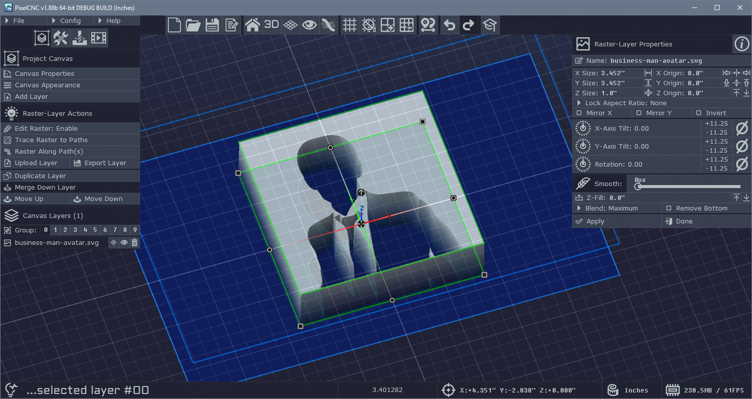
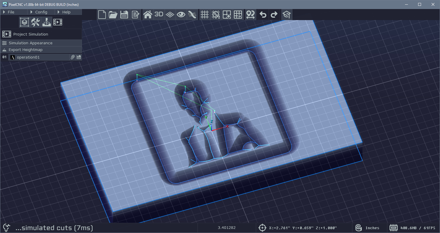
Yes, you can load images/models/vectors and create text and have them subtractively blended with the canvas to create a negative.

For example:


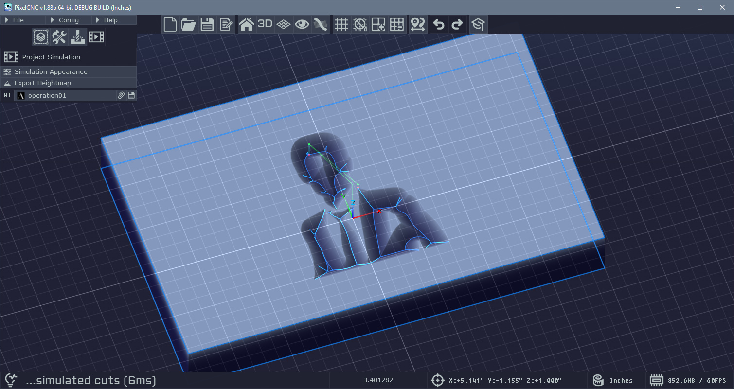
Here an STL model has been loaded, then the canvas Z-Fill is changed to the top of the canvas volume, and the layer's blend mode is changed to Subtractive, which results in:


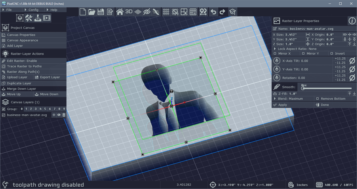
Though what would be better than simply scaling up the model(s) is converting them to a raster-layer (a heightmap) by selecting the model and clicking "Copy to Raster-Layer", then hide/delete the original model layer, select the raster-layer, and click Edit Raster on the left. This will enable the mode for editing the content of the raster-layer that was produced from the 3D model layer. In the raster-editing mode you can then use the Expand/Contract function to properly add some more room for your items. This is the way to go if any of your items' shapes are not particularly round as it will account for all surfaces in all directions, instead of outward. i.e. if you had a ring and scaled up a negative of it the ring would not fit due to the empty inner-area also being scaled up to a larger size. Expand/Contract allows you to push the shape outward from its surface. Be sure that your project's canvas resolution is set high enough to accommodate the fine expansion you want to apply to a raster-layer - before creating the raster-layer from your loaded model.

Then you have several possible combinations of CNC operations that you could use to carve out the acrylic, depending on your machine, what cutters you have available, etc. A 2.5D trochoidal milling operation, with an acceptable Leave Stock value, would be great to rough out the negative. Then you could come back in with a 3D Contouring operation to finish it (Parallel Carving). Alternatively you could use 2.5D Offset Milling with Stepover set to zero so that it only generates surface-cuts, omitting the interior cuts that would only be cutting where trochoidal milling roughed the part out, along with a small Cut Depth for finishing - which would be best using a ballnose cutter of some kind. Or you could just cut the whole thing beginning-to-end using Parallel Carving and a ballnose cutter, possibly with a limited Cut Depth depending on your machine and available cutters, depending on how deep and steep your pockets are.

Feel free to ask further questions if you need help with anything else! Hope this helps :)

 - Charlie

Hi GDavid,

The whole purpose of a bitfile is so that custom games can be shared without being readily modifiable. Someone can reverse engineer them but it was intended to serve as a representation of the game that isn't in readable text form like the scripts.

Connecting to a server using a local bitfile would cause all kinds of issues because the client/server are assumed to be running the same game bitfile. That would be akin to joining a Counter-Strike server while running the Team Fortress client-side code in the Half-Life game engine(s), if that makes sense.

 - Charlie

Been following MM since v0.7, which I downloaded in January of 2020, and you've been able to add a variety of great and interesting features that I never imagined MM would have. Keep up the good work! 

Hi Joe,

The Position Offset allows you to move where along the entire path's length that it positions the raster or text layer. A circular path has a node that acts as both the beginning and end of the path, which means that wherever that node lies is sort of a boundary that an Along Paths won't be able to cross. I realized this a while ago and haven't thought about different solutions yet. For now you'll just have to rotate the paths-layer so that the boundary node is on the opposite side of it from where you want your raster/text to be mapped to.

I think the simplest thing to do is just make it so that the 0.0->1.0 value range goes farther with continuous/looping paths, so that the raster/text can be seamlessly mapped around the entire path. I'll have to take a look and see what needs to be done.

 - Charlie

Ah, yes the size is in the layer's space because it can be oriented at any arbitrary angle, not just 90 degree increments. It wouldn't make sense if it was rotated at say 45 degrees - then which axis would you scale it on? Keeping the scaling relative to the layer allows for these arbitrary rotations.

You could always create a new blank raster-layer below the rotated image's layer and merge down, so that the rotated image is merged with the unrotated blank layer. The new raster-layer will then have the rotated layer natively oriented in the default canvas space, where the canvas XY axes are the same as the layer's.

- Charlie

So PixelCNC automatically scales a loaded image to fill the canvas while retaining its aspect ratio. So if your image is square (width and height are the same) then the layer will be scaled to the smallest canvas dimension, either X or Y. In the case of a canvas that's 24"x48" that would mean that a square image would be scaled to 24"x24".

I'm not sure I follow what you mean about the orientation and resizing. :P

 - Charlie

Alright!

The best I can think of is to copy the canvas to a raster-layer and put that raster-layer on its own layer group for operation's to toolpath off of - set up the canvas size to contain all of your tiles and then duplicate the raster-layer across it. You can use the raster-editing function for 2D tiling to automatically have it replace the contents of the layer with multiples of itself. The caveat is that generating toolpaths will be slower doing it this way - actually toolpathing off all of the tiles simultaneously. Size the raster-layer to the whole canvas (which should be sized multiples of the layer's size) and then use the same multiples for your cols/rows in the 2D tiling function.

Ideally, there would just be an option in the Export G-Code dialog to automatically tile the exported G-code by a specified number of rows/cols and at a set spacing in X and Y between the tiles. I think I could hammer that out pretty quick, in just a day or two. I'll add it to the todo list and see if I can't get it in there for the next update. Then you can just design and toolpath one tile and have the G-code export with copies at each tile's offset position - no toolpathing off all of the tiles at the same time.

Just make sure that your canvas resolution is high enough for holding all of the heightmap pixels at a decent quality level - particularly if you're going to use the raster 2D tiling function.

There might be a utility somewhere out there for automatically tiling an existing G-code program. At least, it wouldn't be something difficult for someone to do - they'd just have to insert some work offsets and repeat the code.

 - Charlie

Glad to hear it! :)

Hi Joe,

Right now the only way to "remove" a tool from the library is to just overwrite it with another tool definition by saving to the slot you wish to overwrite. There's not a way to blank out a tool library slot though.

I do think that for someone who uses PixelCNC the way you do it might be better to just use the new feature for loading tools from the library from the operation parameters interface. You don't need to have any tools defined for a project to create an operation anymore - though PixelCNC will still popup a messagebox about it, but it will still let you create a new operation and assumes you will be loading tools via the new "Load From Library" button that shows on operations' Tool parameter.

 - Charlie

Good catch! I just dug up the old archive for the code that went to v1.0 and yes, the command is never registered with the others but the functionality for it also might not work even if you include it in a bitfile because it sorta just bleeds over into findradius. I'll try to set aside some time in June to go over everything and release a new version of Bitphoria with all the crazy new stuff that's been added since v1.0. Maybe I'll even fire up the master server again and see if we can't track down that long standing server crash bug that always eventually seemed to happen.

Anyway, I'd suggest just using findradius with a big radius for the interim - it should behave virtually the same though it will be a tad slower because it is doing some spatial indexing and distance checks so I'd recommend against having it constantly called by dozens of entities at the same time.

Glad someone is fiddling around with Bitphoria!

 - Charlie

Yeah, it's far from ideal - v1.61b will make it much easier :)

Ah, the only way it appears is to copy the text-layer to a raster-layer with Mirror X/Y enabled (or rotated 180deg) and then create a new raster-layer to merge that down onto. Then you would use that with Along Paths.

so:

  1. Copy to Raster-Layer the text-layer
  2. Enable Mirror X/Y options on the raster-layer
  3. Create a new blank raster-layer below it
  4. Merge mirrored layer down onto blank layer
  5. Use result with Along Paths

A bit more convoluted than I'd like. I'll make sure that both the Mirror options affect Along Paths as well as including a Flip Axis option on the Along Paths so that there are multiple ways to go about it.

 - Charlie

Hi Joe,

The Along Paths function currently only maps layers along the direction the path is created with - and I'm just now seeing that the Mirror X/Y options haven't been included in how it uses a layer either. I'll make sure v1.61b includes the ability to flip the mapping direction on there. I think just an option next to the X/Y Axis mapping direction to flip it would be good. I thought that copying to a raster-layer while the text has Mirror X/Y enabled would create a layer that's 180 flipped and you could use that but that's not the case either. Looks like an impossibility with v1.60b. Dang!

Thanks for catching that one. I'm just working on finishing up a few things and aim to have v1.61b out during the weekend.

 - Charlie

(1 edit)

Hi Joe,

Yeah, for now you just have to make a circle raster-layer to mask the canvas. Super early on before the first release there was a plan to support cylindrical canvas shapes but so much has been built onto everything since then that I'm thinking it's just going to stay the way it is with the canvas being a rectangular shape. After this next release of v1.61b soon the focus will be on the new content library system where users can add content from an online public library where users can share shapes and designs as paths-layers and raster-layers. There will be a base library of shapes like squares, rectangles, circles, stars, arrows, etc... which will make it easy to add these things to a project for whatever purpose, including masking off a canvas for a round project.

To put text on a curve you would create a paths-layer, draw out the curve you want - I prefer to use the curve as the centerline for the text, but you can draw a curve and have it be for the bottom or top of the text. Then set the paths-layer with the curve you want to use as the layer beneath the text-layer you want to conform to it by re-ordering the layers within the canvas layers list. While the text-layer is selected you then use the Text Along Paths function, under Layer Actions on the left side of the screen.

A pretty thorough explanation of how to use the Text/Raster Along Path(s) function can be seen in the PixelCNC Tutorial #03 video here: 

(EDIT: The Along Paths function explanation begins at the 13:00 minute mark)

Let me know if you have any other questions about the Along Paths function :)

 - Charlie

It's had people come and go over the years. I think once I do a real advertisement push (which I haven't done at all yet) then it will be really popping, though by that point I plan to have a whole different forum setup just for the new site. :)

The Tool Library was the product of someone requesting a way to re-use tool definitions in the first place. A lot of changes and new features are the result of user feedback, the more the merrier! I can't promise that every idea or suggestion will make it into PixelCNC but users will have ideas for things I never would've considered - and there's a lot of value to be had from that.

I'll try to add in the ability to directly choose tools for an operation from the library dialog for the next update. Then you will always be able to go back to the Project Tools mode and edit the tool definition if need be, or otherwise use the Project Tools mode to populate the library and update definitions the way it is now.

 - Charlie

Hi Joe,

The Project Tools list is a separate thing from the Tool Library so that if the project is loaded on another computer running PixelCNC the correct tool definitions are present, without requiring a an identical tool library. The library can be re-arranged to change which tools are in your top 10. Would you like it if the Load Library to List showed the library and let you apply sorting to determine which tools are loaded? The main reason PixelCNC limits a project to ten tool definitions is because there's also a limit of 10 operations per project which means the project couldn't use more than 10 tools.

Both limits may change in the future but it will require a bit of a revamp of the whole project file format, which isn't out of the question but not on the near-term list of things to do.

I think a good idea would be to instead allow selecting tools directly from the Tool Library for an operation, and have it automatically place it in the project's tool list where there's an empty tool index, or an index that's not being used by any operations, if it hasn't already been added to the Project Tools list already.

Let me know what you think :)

 - Charlie

Hi Joe,

The canvas and layers default to having their Z-fill set to the bottom, and then layer blend modes default to Maximum. This makes it easy to fill up the canvas with content for relief/emboss style carving projects. For V-carvings and engravings things need to be reversed, Z-Fills raised to the top of the canvas/layers, the layers inverted, and blend mode set to minimum. I've been thinking about how to make it easier to get from one project style to the other without requiring the user to do so many steps. Maybe when they click "New Project" from the File menu it prompts the user what style project they want to make to establish what the defaults for the canvas and layers should be. It's something I'm still weighing options about.

Keep me posted!

 - Charlie

It sounds like you had some properties that were non-default on your layers that were interfering, but if you have default parameters on your layers Z-fill and invert then it's the quick and easy way to create a canvas where the text are pockets instead of islands when creating a new project from scratch. I'd suggest trying it again and make sure everything is set properly because it's important to have an understanding how/why things work the way they do.

  • Canvas Z-Fill to top of canvas
  • Layer's Z-Fill to bottom (default for new layers)
  • Layer's Invert disabled (default for new layers)
  • Layer's Remove Bottom disabled (default for new layers)
  • Layer's Blend mode set to Subtractive

The text-layers are "white on black" for their heightmaps and all that needs to happen is they are subtractively combined with a canvas that has a Z-fill to the top of the canvas. You could also use the Difference blending mode but it can be a little less intuitive when manipulating layers with different Z origins and Z sizes, but it will be functionally the same if your canvas Z-fill is to the top of your canvas and your layers occupy the full depth or height of your canvas (Z origin is at bottom of canvas and Z size is same as canvas).

I'm wrapping up a fix and updating the User Guide and aim to have v1.58b out by the end of the day :)

 - Charlie

Hi Joe,

You need to change how your layers are blending together for the medial-axis carve. Just change your canvas' Z-Fill in the Canvas Properties to the top of the canvas and then change the blend mode for all of your text-layers from the default "Maximum" to "Subtractive". Everything is a height value and it's mathematically adding all of the layers up using the chosen blend mode for each layer.

As for vertical spacing: I have been trying to figure a painless way to integrate multi-line text editing in there but there are some obstacles to overcome but that's been the plan for now, so that you don't need to use multiple text-layers for multi-line text. I'll keep working on that after the new update goes out soon :)

 - Charlie

Hi Ravenclaw,

You can tell PixelCNC to create new projects with metric units under the Config menu in CNC/CAM Settings, toward the top. It will not change an existing/open project from one units to the other and only affects what new projects will be created with :)

 - Charlie

I'd like to see that SVG if you don't mind shooting it over at support@deftware.org

The internal rasterizer that takes an SVG and generates a raster-layer from it might be doing something that we can change, or at least look out for when parsing and rasterizing the vector image.

I'm curious how the Shapes From Paths differs from the raster-layer when directly creating one from the SVG file.

Feel free to send over the SVG and I can take a look and let you know what the situation is with it :)

 - Charlie

Hi Joe,

The medial-axis carve will only cut as deep as the flute length of a V-bit, and only as deep as the corner radius of a ballnose cutter.

Make sure your canvas Z size is deep enough to accommodate the depth of the cuts that are needed - along with the layer's Z size, unless you modify your contour Z to stay within the layer.

For example:


The V-bit is a 90deg 1/2" diameter and has a flute length of 0.25", so that's as deep as it will go. The canvas + layer Z size is 0.25" to accommodate the full flute length of the V-bit.

Hope that helps!

 - Charlie

Yes the price will be going up to $250 once the beta version is released on the new site. Existing users always receive updates free of charge so the best time to get your copy is ASAP if you want to save $30.

You will receive a product key from the new site once I port the latest customers over just before the launch, so keep an eye out for your key in the near future if you do purchase PixelCNC from the current website.

Thanks for the offer to help with the web side of things, I'll keep you in mind ;)

 - Charlie