
On Sale: GamesAssetsToolsTabletopComics
Indie game storeFree gamesFun gamesHorror games
Game developmentAssetsComics
SalesBundles
Jobs
TagsGame Engines

PixelCNC Has Moved: deftware.org

CAM software developed by artists for artists to create unique and original works on a 3-axis CNC router or mill. · By Deftware

Tab placement

A topic by Ynitial created 2 days ago Views: 40 Replies: 4
Viewing posts 1 to 4
(2 edits) (+1)

Hi all,

I’m working on a simple 2D project and I’m running into some limitations with tab placement.

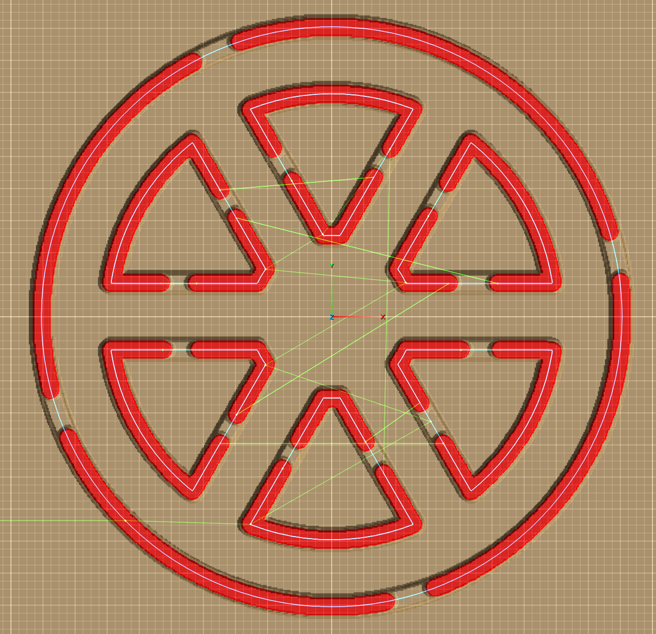
As shown in the screenshot below, the outer tabs are fine. For the inner cut-outs (triangles), however, I’d like each triangle to have two tabs, both positioned on the straight edge. The top triangle already has the tab placement I want.


I duplicated that toolpath for the other five triangles and adjusted the tab settings, but I can’t get all six triangles to match the top one in terms of tab placement. It seems the tabs are being distributed automatically, and I can’t influence where they land.

This leads me to two questions:

  1. Is there a way to manually place tabs, or control the start point / tab distribution along a profile?
    I haven’t been able to find an option for this so far.

  2. As an alternative approach, I was considering adding a small 2 mm-high ring over the triangles center to act as tabs instead of using the built-in tab feature.
    Is this a viable workflow in PixelCNC, and if so, what would be the recommended way to set this up using a simple profile cut?

Any pointers or suggested workflows would be greatly appreciated.

Thanks!

Developer

Hi Ynitial,

Having more control over tab placement is another item that's been on the ever-growing todo list for a while. We're looking at simply adding an offset parameter that allows the user to move where the tabs begin within the distance between two neighboring tabs. This has definitely been something that I'd personally like to see added ASAP as I am always using the profile milling operation and including tabs for cutouts.

The next best thing to manual tab placement would be to use the paths-carving operation. You can use the Trace To Paths function to generate a path with an offset equal to half the diameter of your cutter's flutes. Then manually edit the resulting path to have a gap where you want a tab. Let a profile milling operation do material removal down to where there's enough material left for your desired tab height, and then use the paths carving operation along with the paths-layer from tracing the shape as input to do the final cutout. Just remember that the paths carving operation doesn't allow for any kind of tool offset, being that paths are not considered to have an inside or outside to offset toward or away from the way that 2D milling operations do with their contour input.

Hope that helps! Let me know how it goes, or if you have any other questions or need help with anything else :]

 - Charlie

(1 edit)

Thanks for the insights Charlie, much appreciated!

I couldn’t find a way to add nodes and then removing a specific segment of a shape directly in PixelCNC, so I ended up doing that part in Affinity Designer and then re-importing the vectors. I’d love to learn the pixelCNC native method how for next time.

The result:


Also, having more control over tab placement would be extremely helpful. I’m the guy who moved from Carveco to PixelCNC a while back (we’ve exchanged a few emails), and I wanted to share this use case with you. An offset parameter would help a lot but precise tab control would really make a difference. If you jump to 4:53 in the video, you’ll see what I mean. This kind of control would be especially useful in situations like the above (being able to keep all in 1 path), or the skull/snake tutorial, where parts such as the tail are quite fragile.

Thanks again for taking the time!

Developer

Hi Ynitial,

That looks good!

What I do to create gaps in paths in the paths-editing mode is hold CTRL for node placement, left-click on the path to create nodes, and then while holding SHIFT you can right-click nodes to remove them and the section of path they're on, whereas right-clicking nodes on a path without holding SHIFT only removes the nodes from the path without breaking the path up.

Removing nodes without breaking the path can be useful for rounding out corners too. Simply hold CTRL and place nodes next to a corner node, one on each side, and then right-click the corner node. The path will automatically interpolate between the two nodes that were created next to the corner node.

The path-layer editing mode can be super handy for doing all kinds of things and I highly recommend becoming familiar with it. The '?' button at the top-right of the PixelCNC window when in the path-editing mode will show you all of the modifier keys for drawing and editing paths.

Hope that helps! Have a good day :]

 - Charlie

(+1)

Will do Charlie, thanks for your replies!