Hi I found a bug in your game
While a mission of Penny when player have mini game match
When time is gone ,the game got crash
I hope my bug can improve your game and patreon version will be available for public 
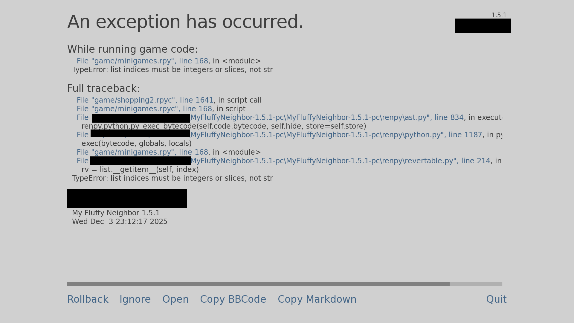
Kamir1
Recent community posts
I use for ROM 2 tools GPT and Libre office calc
For example i try made sound track of zelda ( Overworld 1986) , so GPT create me a list of hex for note . I have midi and I was crate a data in libre and coppy and pasting for 3 ROMS(16 s per one ROM) this method is suffice me
I saw your last pixel art and You used decoder 8 to 255 and you used logic ,for this , why ? You can use rom first 00-FF make column second 00-FF row and one 3 state buffer per enable ^^
I hope that it was helpful
Hello , how We can make a sound logic in new version , We have 2 ways
First is hard , but satisfaction . Make a special logic 8 bit for Pitch and 4 bit for Volume
This solution is very big and slow the simulation
But We can make a second way compact , and easy to copy
Use ROM first 8 bit for Pitch and second 8 bit split to 4 bit for Volume
Ok , but how make a logic for this , It`s simple 
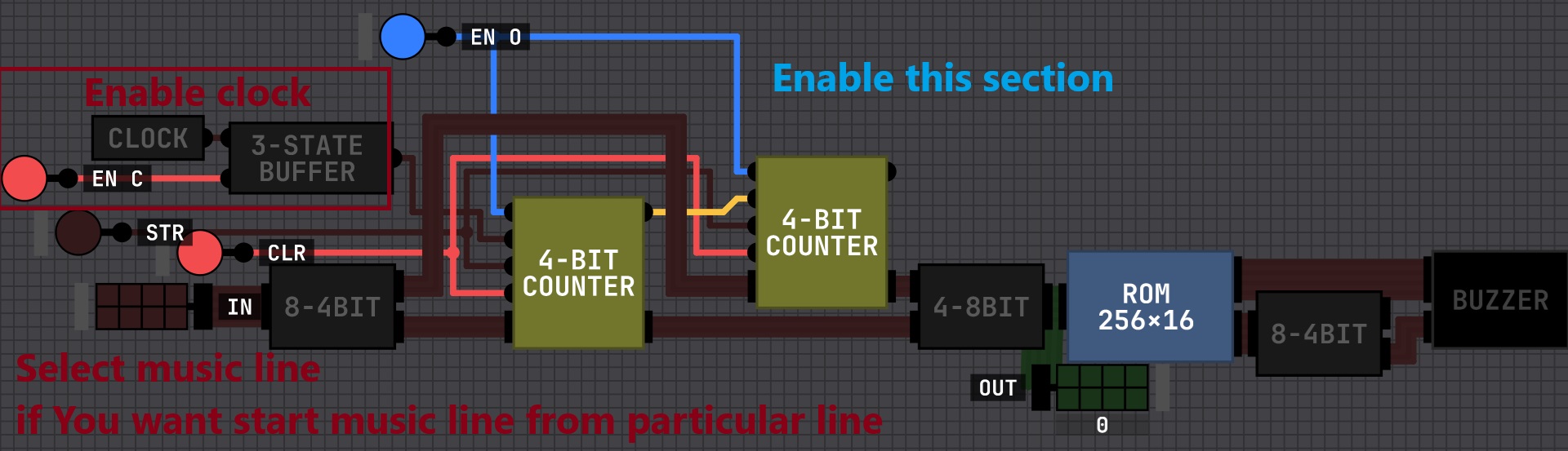
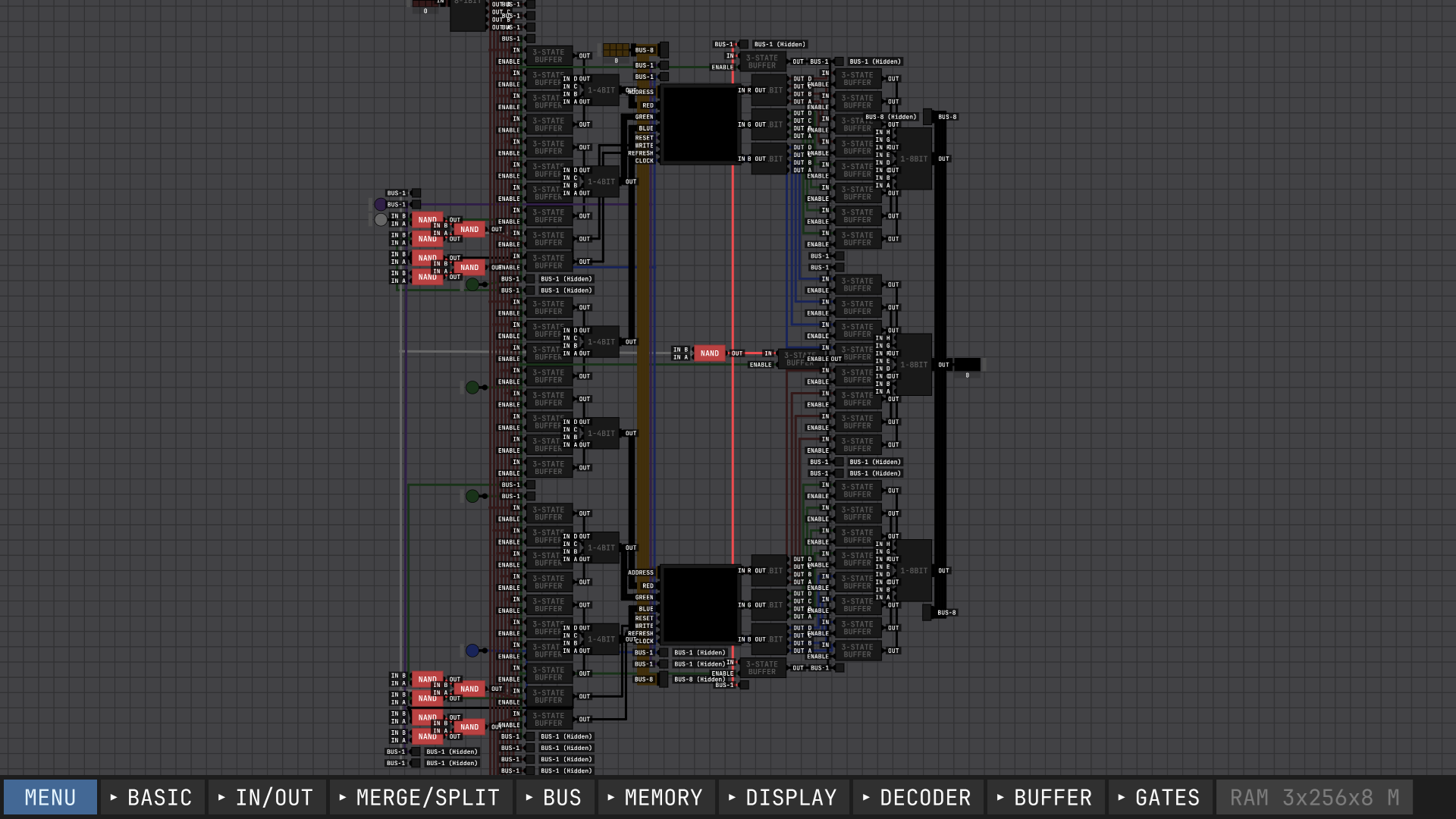
I have a tip for You , because Your project will be big the optimisation will be helpful
Add 3 state buffer before operation logic , why it will help because when You add data on data bus simulation in first step calculate all gate
(for example one gate one tick now you have 5 * 16 = 80 ticks but if you will only one You will need only 16 ticks )
And one more AND gate need 2 NAND but You can use one 3 state
on screenshot You can see how I realize it
first line 3 state allow data input second 3 state make AND gate logic
I hope it will be helpful
I had a stupid idea
We have logic
We have graphic
But We don`t have audio
How can be look , like a LED diode 1 input data (volume data) and when You click right on them You will change a characteristic of sound (saw-toothed mode, sinusoidal mode , etc ) maybe some one can take my idea and upgrade them XD , ok I`m back to my project
Wow your project is very impressive
But i have a few question
Because you said "based off of the 6502 " why your register have a special logic ? (A register in mos 6502 have only 1 output connected to ALU and 3 input 8 bit data SB/ADD (Super Bus / Arithmetic Data Dowland ) and 0/ADD (0 [00000000] /Arithmetic Data Dowland )) but your A register have INC (I don``t have idea ) mode , DEC ( i think is decimal mode) .
Your ALU have only adder and inverter for subtract , don`t have a decimal , and or shift right modes but probably You don`t need this yet
your "Compute " block I think is "Random Control Logic"
Your "Stack" module is very well done but is different from Stack pointer Register from mos 6502 (don`t have second output and your is connected directly to data bus I see )
Be honest You make a great project =D
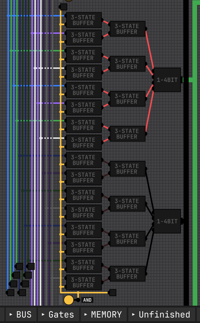
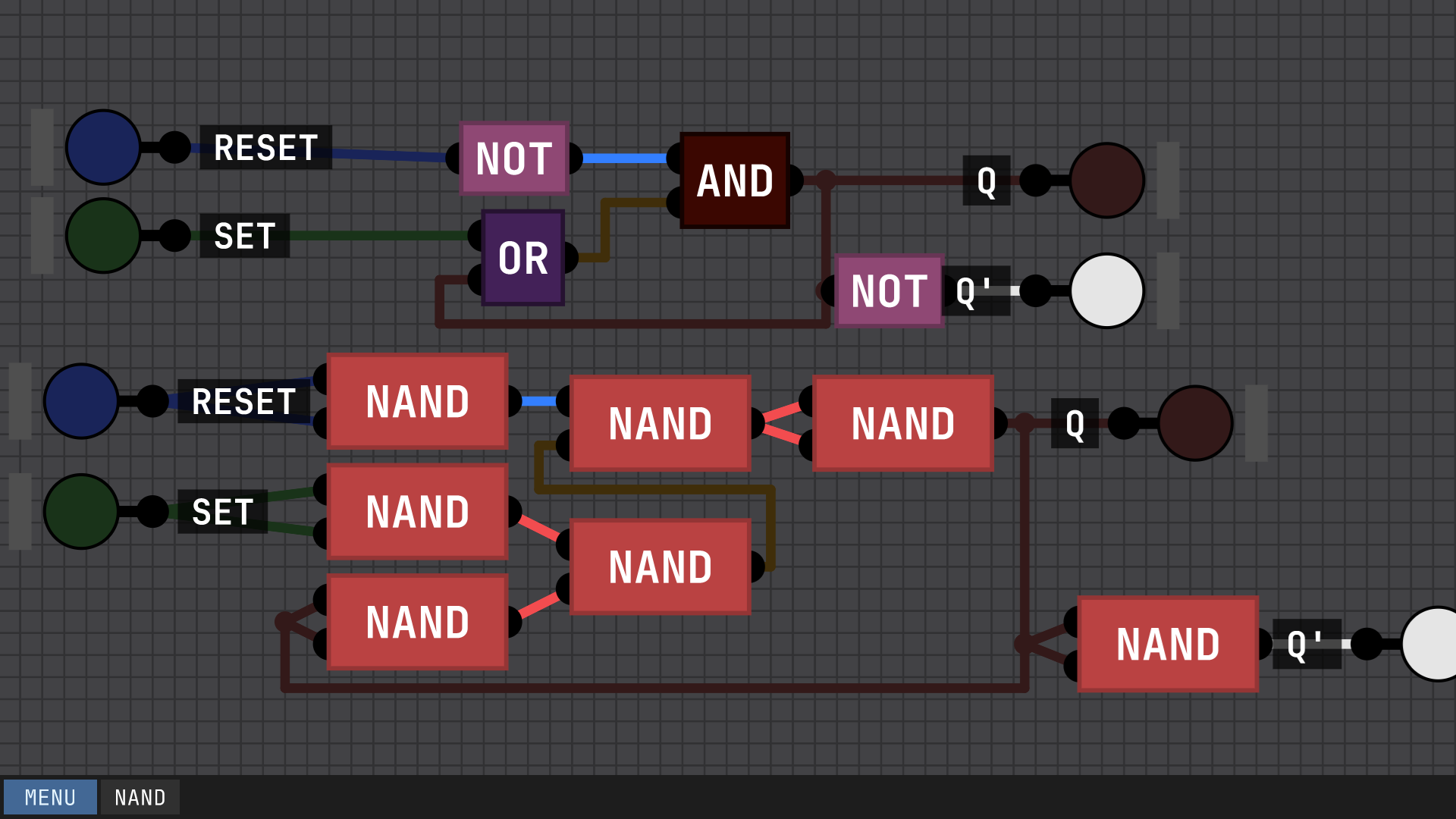
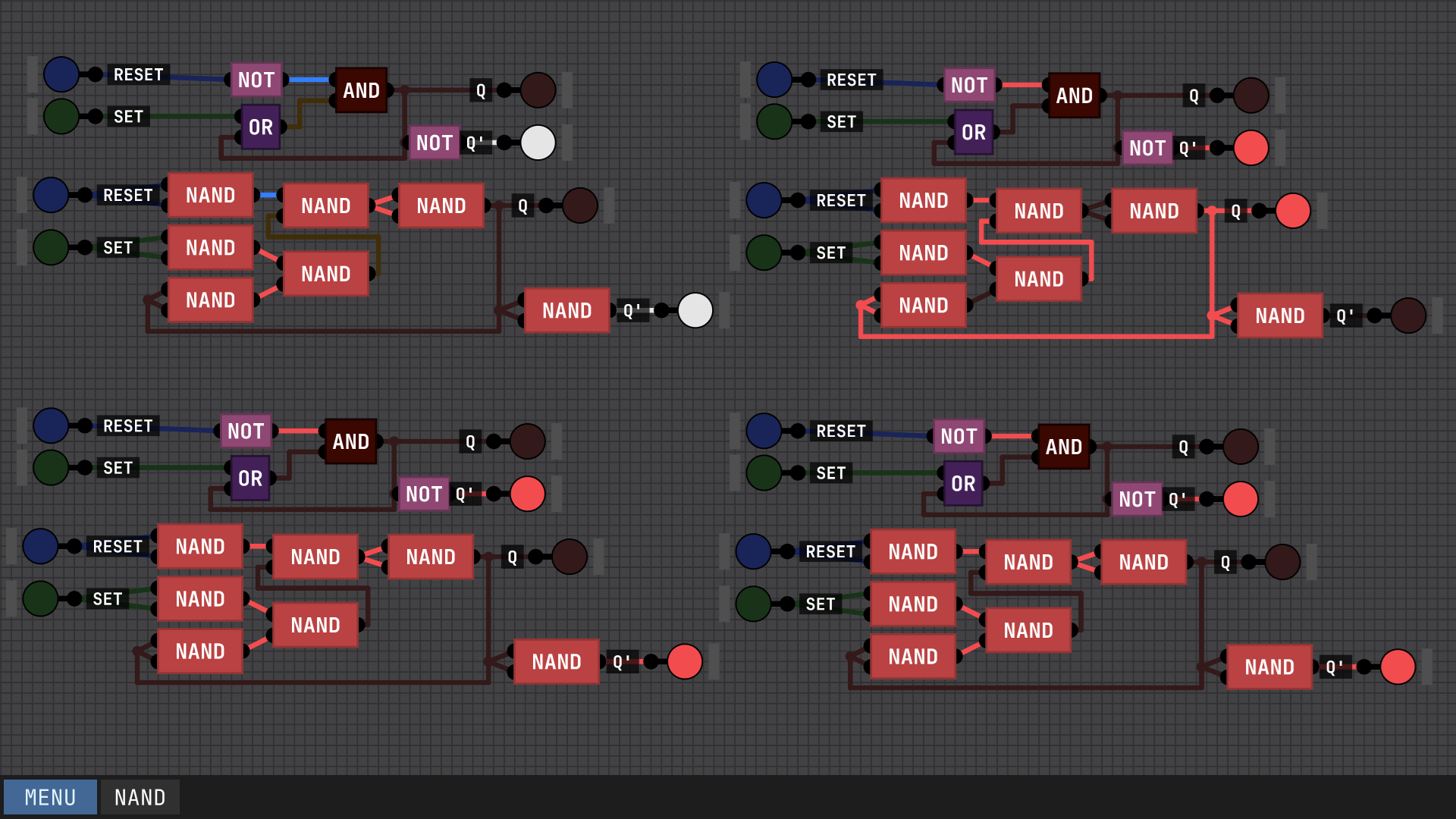
XD I understood You , now I almost done ALU in mos6502 but I use only NAND some times looks like a pasta , BUT WORK as well XP
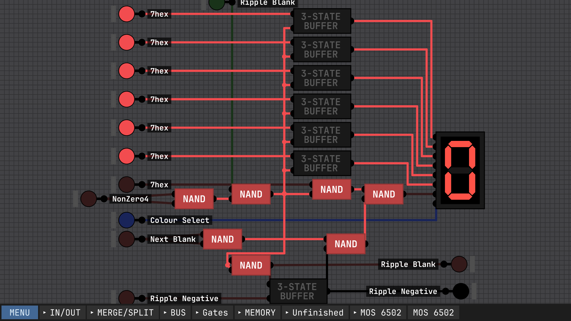
About RAM Use RGB 8pin for address and 2x4 bit for data (more data in one place ) and if you use only data without address You will got a register ( Load pin conect to save refresh and clock , Read use 2 4to1 bit and use 8 3state buffer)
But first You must optimize your current logic for example You use a lot of XOR / EOR , but if I good remember you made it from 2 not one AND and 3 other gate but You can make it use only 4 NAND , less gates = quicker simulation , and one more the simulation see user use a special gate for example AND gate so simulation must stop and load AND gate simulate them back to current simulation, but if you use NAND the simulation don`t must stop because you will use basic brick
Output can only have one connection , and you use OR gates , but if you use 3 state buffer you can make 3 type of signals [1 0 no connection] no connection allow you connect multiple signals to output BUT only one can be on !!!
if you have 8 cell memory you only need 8 3 state buffer (one per cell) address pin connect to enable data to IN and finally you will get a some extra steps in simulation =D
if You want I can send you my realisation of RAM
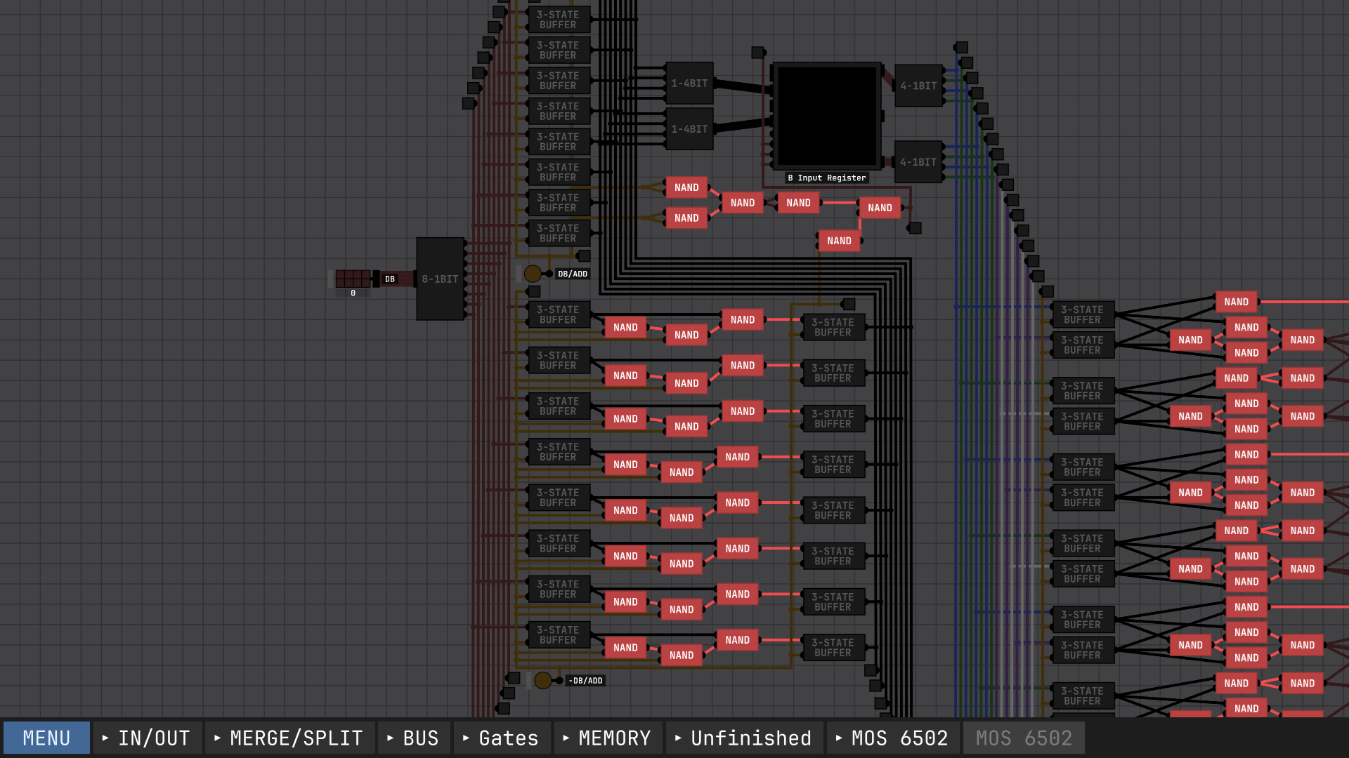
I tried upgrade your RAM 256x8 , because You don`t use a blue channel I was thing if I combine to two RGB I can use this to make another space to save information , so I made it but when I was test it I found a small mistake XD if I try to save data on blue channels I clear previous data on R nad G data slots , now I must add flip flop before RGB to save information on n Address add new information and save them , meybe I can use 1 less RGB screen but I must add 96 gates
This picture show You what I tried to do XP
Use trick with RGB display memory
https://itch.io/t/4780694/gigabytes-of-ram-are-now-possible


