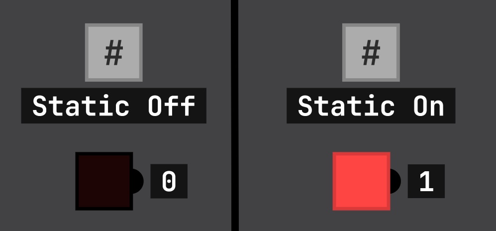
That is just a chip I made that doesn't have any inputs or outputs. You can create one by dragging a single NAND chip into the scene and clicking SAVE CHIP. Then, you can name the chip anything you want (for example: #) and color and resize it however you like (by then clicking CUSTOMIZE)
A member registered Apr 12, 2025
Recent community posts
Digital Logic Sim community · Created a new topic Patreon and itch.io aren't the only ways to support Sebastian!

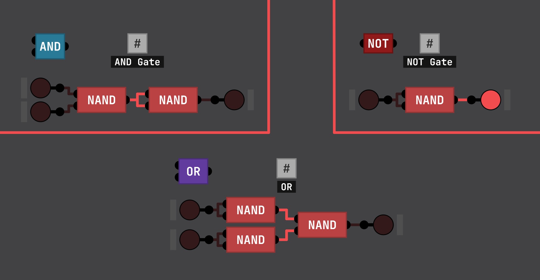
Digital Logic Sim community · Created a new topic Can't find the AND, NOT and OR gates? Here is how you can get them!