Indie game storeFree gamesFun gamesHorror games
Game developmentAssetsComics
SalesBundles
Jobs
Tags

PixelCNC Has Moved: deftware.org

CAM software developed by artists for artists to create unique and original works on a 3-axis CNC router or mill. · By Deftware

How bout a test image

A topic by Donnie created Feb 11, 2018 Views: 443 Replies: 7
Viewing posts 1 to 7

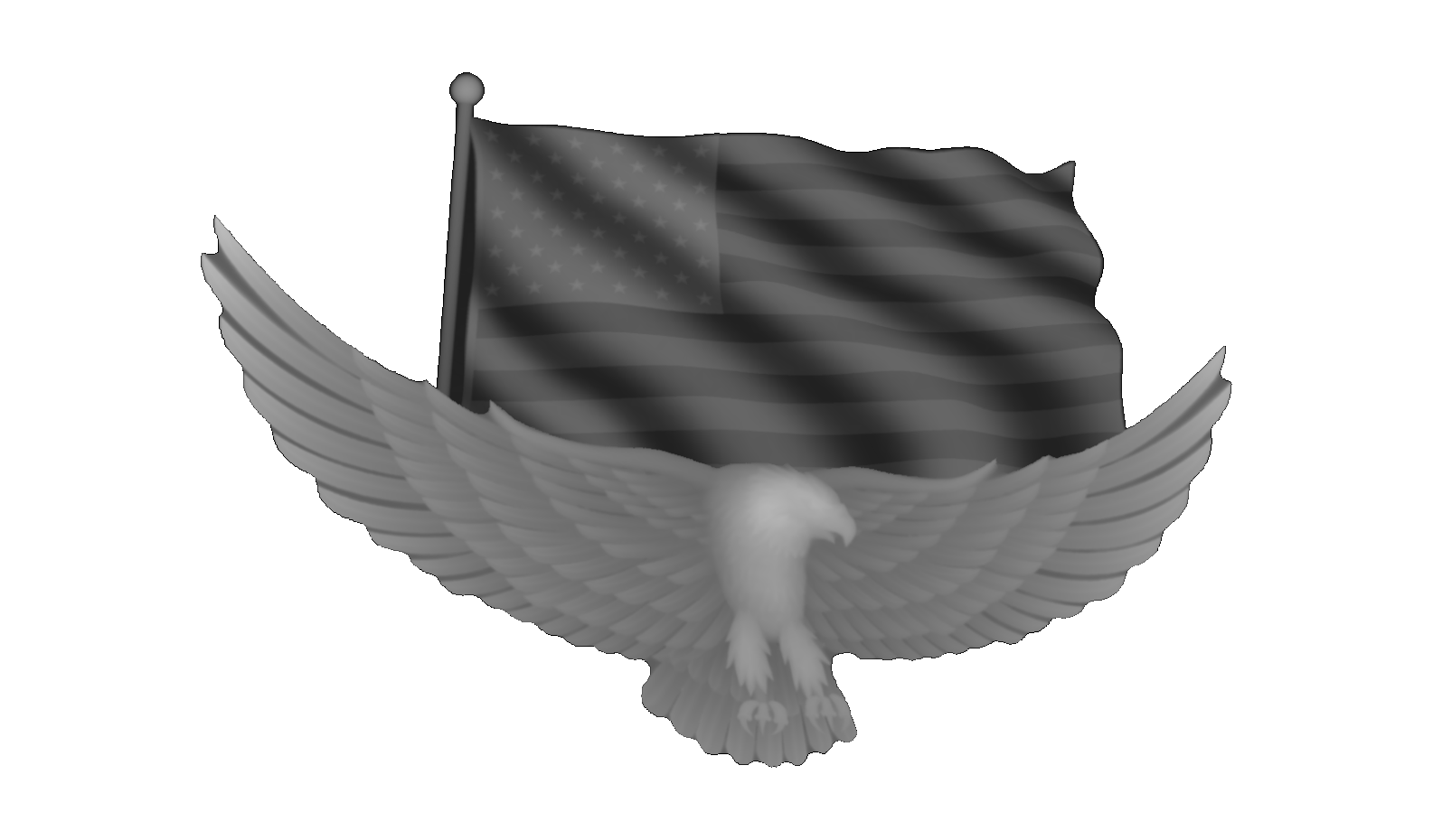
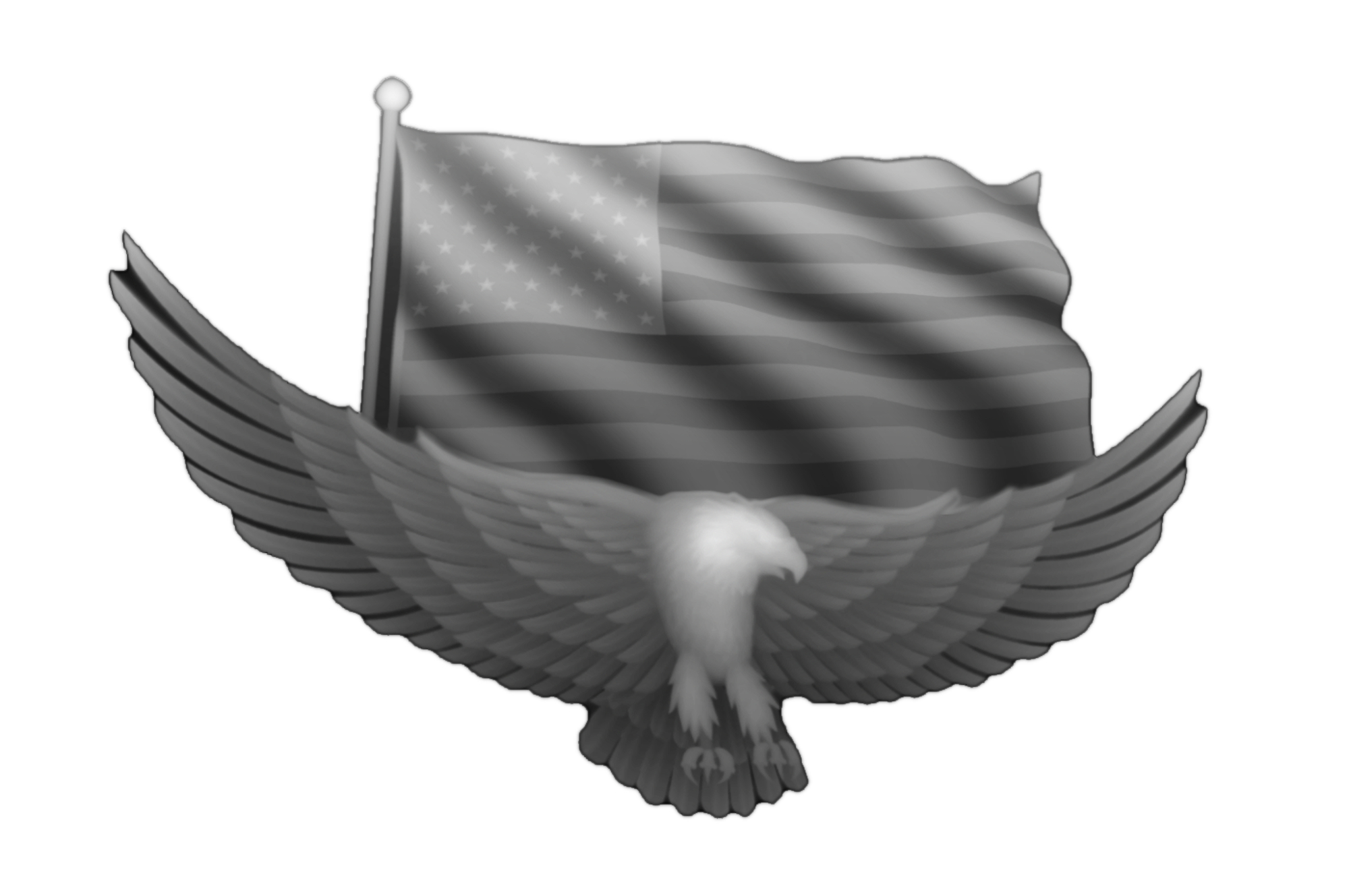
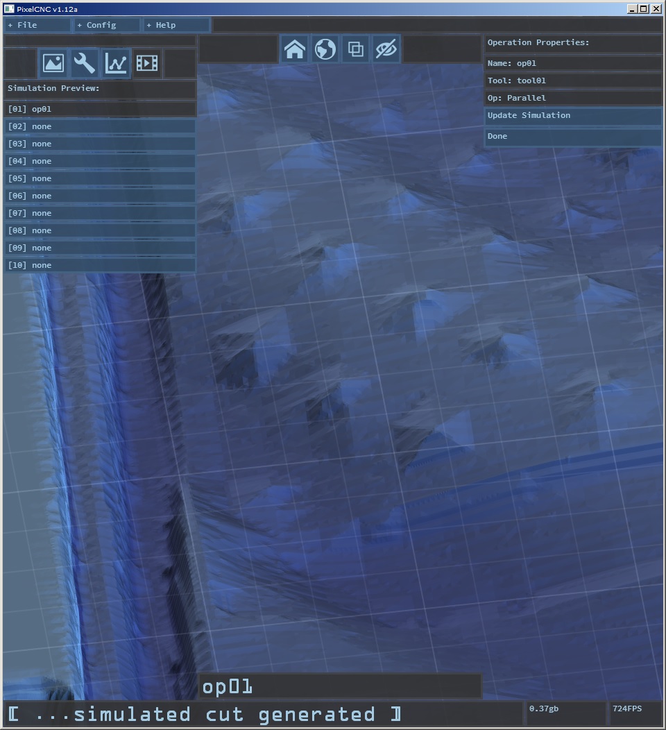
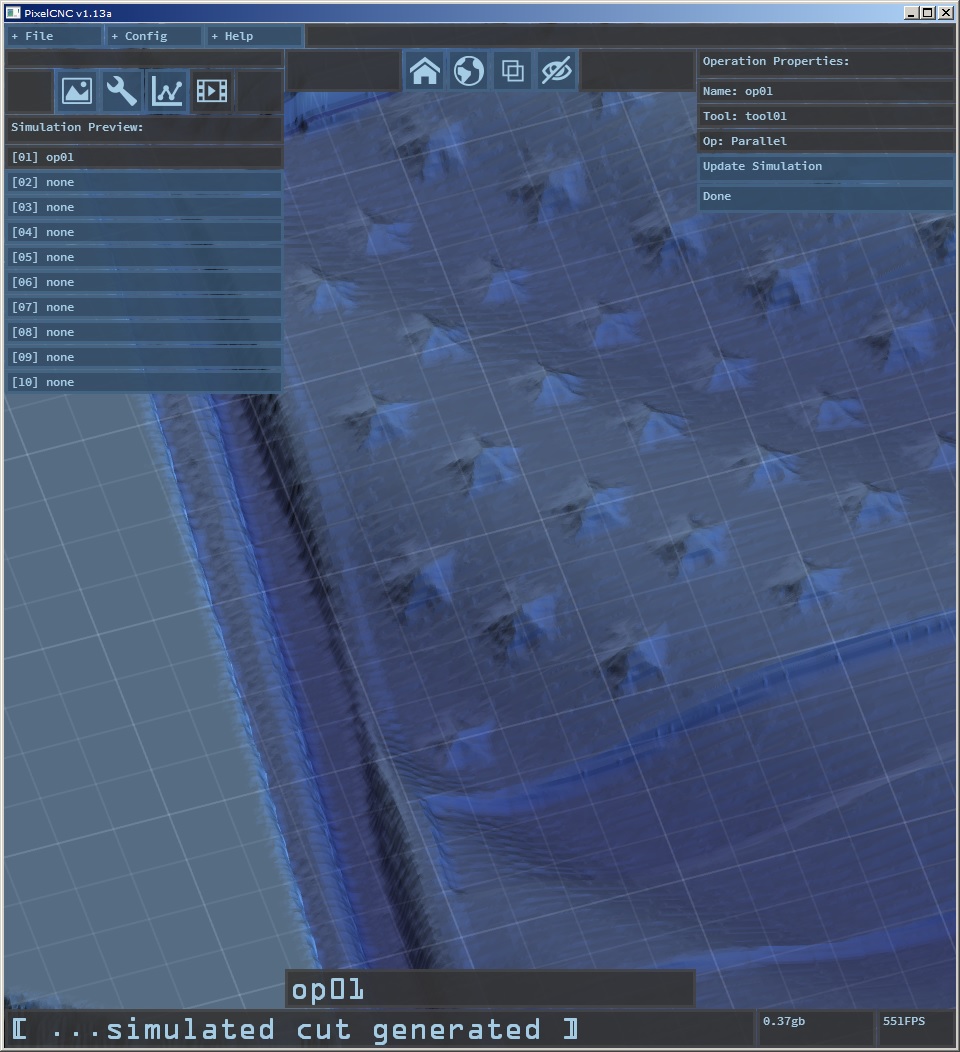
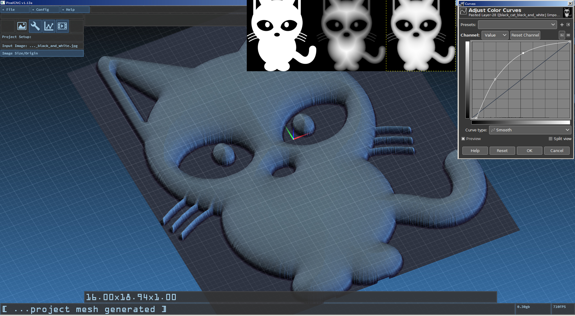
Here is an image that I convert from a .STL image to a .PNG.  I would be curious to see what setting you would use to get the best output from PCNC.  When I tried using PCNC with this image, the tool paths seems to be a little rough.  I tried with a 1/8" endmill, .05 setover at both .25 and .50 max depth.

Thanks,

Donnie

Developer

Hi Donnie. Yes, this image has some nuanced details that don't come through very well with the v1.12a meshing threshold function. I just spent the last hour tweaking the subdivision thresholding algorithm to better handle tiny details. This will affect meshes overall, which are used for the loaded image preview, the CAM toolpath generation algorithms, and the simulation preview system. The end result is a hit on performance/speed, but I think that the end justifies the means.


Initially I tried tweaking your image, to increase the contrast somewhat. I had to do this separately for the flag and the eagle because they're occupying different ranges of gray, somewhat bringing them closer together, but then to create a cool delineation between them I added a slight gradient. To the flag so that the bottom is a tad deeper than the top of the flag, and then a radial gradient on the eagle to make it's top edge a bit raised as well. The end result is better use of the available range of values, which can be tricky because obviously you want the eagle to appear ontop/infront of the flag, this helps to trigger the mesh subdivision because it operates on the image values as opposed to the physical dimensions of the project itself (i.e. increasing project Z depth won't trigger mesh subdivisions).

At any rate, the v1.12a subdiv thresholding was not sufficient:


The same project size/tool simulation in v1.13a:


As tempting as it is to put this out there ASAP I'm going to sit on it for a few days and see what else comes up so I can bunch all the bugfixes/changes into v1.13a. I did also find a bug with the project saving regarding the invert project image mode, so that's fixed in v1.13a as well. If nothing else comes along in the next few days I'll release it anyway.

Thanks!

First off, simple question...Do you go by Charlie or Charles? 

I understand what you are doing with the tweaking.  Currently, the program speed is not problematic at all so I think you can go for increasing sub division and other tweaks at the expense of speed.  Waiting for items to render is much preferable to not having clean conversions.  Maybe, at some point, putting in a time estimate for render would keep folks from thinking that the program has locked up.

I spotted the invert option issue and was going to add it to the issues list.  No need now.

This next suggestion is from my perspective, others may have a different opinion.  What you described with the way you tweaked the picture is nice but I am a just a basic Photoshop user.  I know enough to be really dangerous.  I had already played with the contrast/brightness but the gradient thing is outside my knowledge level at the moment.  The more that you can do to make PCNC handle the adjustments without having to use 3rd party software is better.  To make the product better and adoption by users easier, they will want to load, adjust, output and carve.

Thanks for the hard work.  Looking forward to getting my hands on the new version.

Donnie

Developer

Hi Donnie, 'Charlie' is preferable - and 'Chuck' is offensive ;)

One idea that I have further down on the todo list is the ability to manipulate the histogram 'curves' of an image. The plan is to allow users to load simple black/white images and generate a distance transform of the image - where all of the pixels are replaced with a gray value depicting their distance to the nearest black/white edge. With this distance value I can then let the user sculpt a Z function to apply so that they can effectively generate an interesting depthmap from a simple black/white binary image.

For example:


There would be something similar to the graph in the top left that lets you remap the center distance field result into any depth-function you plot on the graph using a spline type curve or something. This would let you create neat concentric ripples or nice ornamental trim, etc.. But just having basic image manipulation, and even simple text and shape plotting would be great too, which would be pretty easy to do quickly if I did a basic GPU based image editor that had this sort of post processing functionality applied to the final result that PixelCNC would then perform its magic on.

Thanks for the input!

Oh Yea!!!!!!

Charlie,

Nice work. You mostly talk about your workflow being more efficient and I really see it as more fun, and making the whole cnc experience more fun. Can the program export a 3d mesh or solid?  Maybe a future upgrade? Imagine I want to make a design where the center is from a picture, and the frame is modeled in a 3d cad and the 2 can be joined and toolpathed.

Jerry

Developer

Hi jbri, thanks for your feedback :)

You say 'export' but do you mean 'import' 3D geometry into PixelCNC to CAM in combination with an image? I can definitely add exportation of the meshes that PixelCNC generates for toolpathing, to multiple formats (i.e. OBJ and STL, for starters).

For importing 3D geometry I could render it to a depthbuffer texture and download that into PixelCNC's memory for working with as an actual depthmap. One of the big goals for down the road is to have a bit of editing functionality, a sort of studio mode where users can import multiple images, both raster/pixel and vector and create shapes and geometry to layout on their design, and then they can go ahead and create CAM operations and generate toolpaths for that. This is a v2.0 sort of feature. In the meantime I'm looking at optimizing everything and getting the operations and overall interface as solid as possible and make what PixelCNC currently has to offer more user-friendly.

Thanks again!

(1 edit)

I like your export and import ideas. And I think there is value to software that can do the cad mechanical square plate with mounting holes in the corners, with precise locations and diameters dimensioned out for example, and yet also do the swoopy artsy stuff on the same plate that does not have to be super precision mechanically. A hybrid of what you have and a simple usable cad all in a super slick workflow. Just giving you ideas, you have the helm captain. I haven't thought it through fully.


I can accomplish  this with 2 programs run on one part, but you are bringing cnc out of the 80's and paper tape readers and such  :-)

I am trying to think of the worst workflow I have seen like 4 or 5 programs to process 1 gcode program   ....

Jerry