Indie game storeFree gamesFun gamesHorror games
Game developmentAssetsComics
SalesBundles
Jobs
Tags

PixelCNC Has Moved: deftware.org

CAM software developed by artists for artists to create unique and original works on a 3-axis CNC router or mill. · By Deftware

Not seeing anything in Simulation mode

A topic by billb0169 created Feb 11, 2018 Views: 393 Replies: 6
Viewing posts 1 to 6

Not able to see any toolpaths, geometry etc in simulation mode. Am I doing something wrong?

Operations:


Simulation:


Developer

Hi Bill, I believe that the problem is that your cut depth is too deep for your project, at least with the horizontal operation. What happens if you try a different operation, like a parallel path with the same step size? This would narrow down the problem to the horizontal operation itself, and (almost entirely) eliminate the possibility of the problem being a systemic issue - localizing it to the operation itself. There's the possibility that even if your project has a 0.1mm dimension on the Z axis that the image itself isn't exactly 0,0,0 RGB black on the background, which would cause the 'bottom' of the project to not fully reach 0.1mm deep, and instead be something less - which is a problem that we'd know to be the situation here if you were to try a smaller cut depth and it caused a toolpath to be produced (e.g. try a 0.05 cut depth with the same exact project setup).

The horizontal pass is a bit of a work-in-progress, and can be rather temperamental at the moment, ultimately requiring a complete re-work due to the fact that it has issues properly organizing the horizontal plane contours it calculates to piece together a toolpath. Aside from that, even when it does work properly it will only produce cuts at 'cut depth' intervals up to 'max depth' - provided that the input image has dark enough areas to reach at least 'cut depth' for the current project's Z size. So, if no part of the project is even 'cut depth' deep then it won't produce any toolpath. The project must always be exactly as deep, or deeper, than the cut depth itself - for the horizontal operation. If your project is 1.5mm deep and your cut depth is 1.0mm then you can expect the horizontal operation to only generate a toolpath that removes material at the -1.0mm Z depth, but no deeper. In other words: it won't automatically detect the next deepest level after -1.0mm, because there's not necessarily such a thing being that the input image is really just a varied surface/topography: it doesn't know that there's a 'top' and 'bottom', it just see a heightfield which it generates a toolpath to incrementally remove material from at successive cut depths that do not go deeper than the input image or max depth value.

So, a 50% solid gray input image that's used to create a project with a 1.0mm Z depth wouldn't produce any toolpaths with a horizontal operation that has a 1.0 cut depth - because no part of the solid gray image at that project depth would yield any areas deep enough to remove material from. The 50% gray would mean that the deepest part of the project is only 0.5mm deep, and a horizontal operation with a 1.0mm cut depth will produce toolpaths only in areas that are at least 1.0mm deep.

Another example, just to paint a clearer picture of the horizontal operation's behavior, would be the toolpath generated from a solid black image for a project that is 2.5mm along the Z dimension. With a horizontal operation that has a 1.0mm cut depth this would only produce two Z layers of concentric toolpath contours, one at -1.0mm and another at -2.0mm, leaving 0.5mm of material leftover due to the fact that the horizontal operation only creates toolpath contour layers at 'cut depth' increments along the Z axis, and does not exceed the 'max depth' parameter or the project's Z depth.

If you can determine that it's not an excessive cut depth value then we'll be able to investigate further, but right now I'm pretty confident this is just a cut depth error - one which I should add some kind of notification when it's the reason no toolpath is being produced.

Hi,

Reloaded the saved project and changed the cut depth to .05 but the program hangs when I hit apply (not responding). Can see the status is stuck at generating horizontal milling operation. Log dump below.

0.034 0.034  [ PixelCNC v1.12a - Feb  7 2018 ]
0.034  [ Charles Van Noland - deftware.itch.io/pixelcnc ]
0.034 0.034 --- initializing ---
0.034 configuration...
0.035 ...loaded configuration
0.035 system...
0.095 8 logical cpus detected
0.095 >> starting thread00...
0.095 >> starting thread01...
0.095 >> starting thread02...
0.096 >> starting thread03...
0.096 >> starting thread04...
0.096 >> starting thread05...
0.096 >> starting thread06...
0.096 >> starting thread07...
0.096 >> starting thread08...
0.097 >> starting thread09...
0.097 >> starting thread10...
0.097 >> starting thread11...
0.097 >> created mutex #0
0.097 >> created mutex #1
0.097 image...
0.097 >> created mutex #2
0.117 input...
0.117 render...
0.118 >> r_begin: allocated 260.0mb vertex buffers
0.119 GL_VENDOR: Intel
0.119 GL_VERSION: 3.0.0 - Build 20.19.15.4549
0.120 font drawing...
0.121 loaded ".\fonts\system.png" (256x128@4)
0.122 ...loaded font "system"
0.123 loaded ".\fonts\fixedsys.png" (256x128@4)
0.124 ...loaded font "fixedsys"
0.124 loaded ".\fonts\source_code.png" (256x128@4)
0.125 ...loaded font "source_code"
0.125 loaded ".\fonts\latha.png" (256x128@4)
0.126 ...loaded font "latha"
0.128 loaded ".\fonts\latha_big.png" (512x256@4)
0.130 ...loaded font "latha_big"
0.131 loaded ".\fonts\tahoma.png" (256x128@4)
0.131 ...loaded font "tahoma"
0.133 loaded ".\fonts\tahoma_big.png" (512x256@4)
0.135 ...loaded font "tahoma_big"
0.135 loaded ".\fonts\verdana.png" (256x128@4)
0.136 ...loaded font "verdana"
0.138 loaded ".\fonts\verdana_big.png" (512x256@4)
0.140 ...loaded font "verdana_big"
0.141 loaded ".\fonts\ocr_a.png" (256x128@4)
0.141 ...loaded font "ocr_a"
0.143 loaded ".\fonts\ocr_a_big.png" (512x256@4)
0.143 ...loaded font "ocr_a_big"
0.144 loaded ".\fonts\icons.png" (256x128@4)
0.145 ...loaded font "icons"
0.147 loaded ".\fonts\icons_big.png" (512x256@4)
0.148 ...loaded font "icons_big"
0.148 view...
0.148 mesh...
0.148 >> mesh_init: allocated 1.44KB meshes array
0.149 >> mesh_init: allocated 36.00mb polyline verts array
0.149 toolpath...
0.154 cam...
0.154 >> created mutex #3
0.154 project...
0.154 tools to metric defaults
0.154 gui...
0.154 ...program initialized
0.154  ( 296.0mb currently allocated )
0.154 --- entering main loop ---
0.255 >> unts:2 scale:0.039370,2.000000 subdiv:0.100000
0.255 >> r_modelnew 0
0.255 >> copying 1260 verts to model buffer
0.255 >> ...done
0.256 created model: 1 draws, 1260 verts
0.256 >> axis regen 25.400000
0.256 >> r_modelnew 1
0.256 >> copying 6 verts to model buffer
0.256 >> ...done
0.256 created model: 1 draws, 6 verts
10.562 >> units = millimeters
10.562 >> ge]
10.563 img_read: 1280x706x4
10.563 >> setting project input...
10.618 >> laplace
10.835 >> img_scalarblend: 1280x706, 1280x706, 1.000000x1.000000
10.922 >> project_updatetexture done
10.922 >> simulation depthmap size: 1357x748
10.931 >> img_scalarblend: 1280x706, 1280x706, 1.000000x1.000000
10.969 >> halving 2955.6ppi...
10.969 >> halving 1477.8ppi...
10.969 >> halving 738.9ppi...
10.969 >> halving 369.5ppi...
10.969 >> halving 184.7ppi...
10.969 project pixels/inch = 92.4
10.970 >> r_modelnew 2
10.970 >> copying 4 verts to model buffer
10.970 >> ...done
10.970 >> copying 4 verts to model buffer
10.970 >> ...done
10.970 >> copying 4 verts to model buffer
10.970 >> ...done
10.971 >> copying 4 verts to model buffer
10.971 >> ...done
10.971 >> copying 4 verts to model buffer
10.971 >> ...done
10.971 >> copying 4 verts to model buffer
10.971 >> ...done
10.971 created model: 6 draws, 24 verts
10.971 >> project_setinput done
10.971 >> [toolpaths]
10.971 >>  0->name = op01
10.972 >> [simimage0]
10.973 >> generating input image mesh...
10.973 >> getting corner verts...
10.973 >> downscaling input image... 320x176
10.973 img_read: 1357x748x4
10.973 >> toolpath_compilepaths: 0 0.101000 horz
10.978 toolpath[0]: generated 1 moves from 0 paths and 0 vertices
10.984 >> r_modelnew 3
10.985 >> copying 1 verts to model buffer
10.985 >> ...done
10.985 >> copying 1 verts to model buffer
10.985 >> ...done
10.985 created model: 2 draws, 2 verts
11.162 >> blending downscaled image...
11.162 >> img_scalarblend: 1280x706, 1280x706, 1.000000x1.000000
11.200 >> dividing up mesh...
11.268 >> reallocated 12.9mb triangle buffer
11.314 >> reallocated 20.9mb triangle buffer
11.386 >> reallocated 33.9mb triangle buffer
11.514 >> reallocated 54.8mb triangle buffer
11.706 >> reallocated 88.7mb triangle buffer
12.393 >> setting triangle apex verts...
12.477 mesh_fromimage: created bitree mesh, 2262166 nodes (1.504000 elapsed)
12.496 >> r_modelnew 4
12.796 >> r_end: reallocated 110.1mb model vertex buffer
12.796 >> copying 3393252 verts to model buffer
12.822 >> ...done
12.987 created model: 1 draws, 3393252 verts
87.787 >> freeing camop[0]
87.790 >> freeing pathmodel[3]
87.790  [ 7 ] = T1 F33 S20000 D0 SO0.019600 ZDOC0.050000 ZBOT0.100000 ZTOP0.001000 SAFE0.100000 AUX[ 0.000000 0.000000 0.000000 ]
87.798 - - - - - - - - - CAMOP_HORIZONTAL - - - - - - - - -
87.798 >> convolving input image with tool[1].surface...
87.900 >> ...done
87.900 >> horizontal toolpath: z_top = 0.000000, z_bot = -0.100000 (z_step = 0.050000)
87.900 >> horizontal contouring: z = -0.050000, img_z = 0.500000
87.951 >> getting corner verts...
87.952 >> downscaling input image... 10x5
88.103 >> blending downscaled image...
88.103 >> img_scalarblend: 40x22, 40x22, 1.000000x1.000000
88.103 >> dividing up mesh...
88.110 >> setting triangle apex verts...
88.111 mesh_fromimage: created bitree mesh, 16372 nodes (0.160004 elapsed)
88.113 >> ...contoured dist:0.00, polylines:4
88.146 [ ERROR ] camop_horizontal: ditched polyline 2:2

Developer

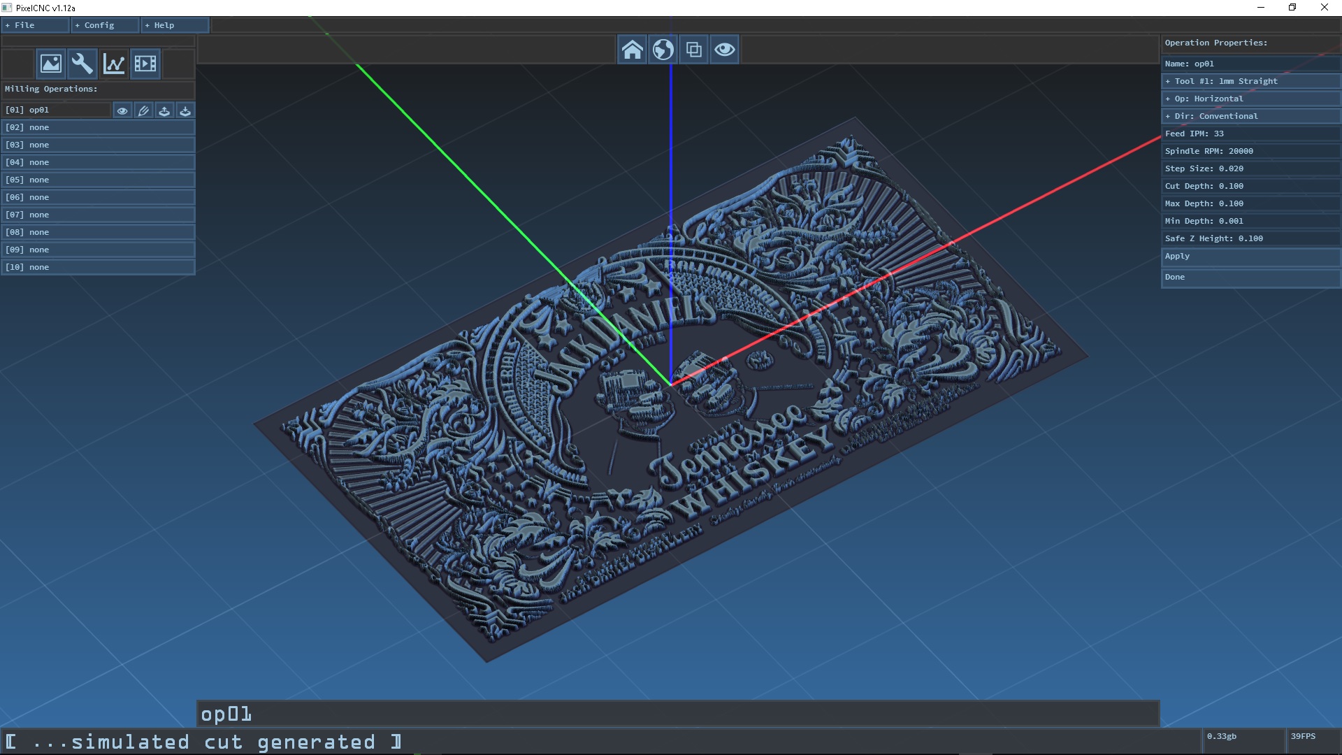
Hi Bill, another thing I noticed is that your tool is a 1mm diameter bit but your project is only ~10x5mm in size - judging by what appears to be the default grid with major lines every 10mm and 2mm subdivision lines.  The red/green/blue axes are also 1" in length, so the project is pretty tiny. There doesn't appear to be any areas inside of a project that small that the 1mm bit would be able to remove material from without infringing on the parts of the input image that aren't supposed to have material removed from them, maybe a peck or two around the wrists holding the glasses? The horizontal milling operation will only remove material where it can be removed from without cutting into parts of the project that rise through the depth of each cut layer:


I put pixelcnc back in inches mode then reloaded the image and set the cut depth to .05 but still hanging when I hit apply in Ops config.

0.034 0.034  [ PixelCNC v1.12a - Feb  7 2018 ]
0.034  [ Charles Van Noland - deftware.itch.io/pixelcnc ]
0.034 0.035 --- initializing ---
0.035 configuration...
0.035 ...loaded configuration
0.035 system...
0.097 8 logical cpus detected
0.097 >> starting thread00...
0.098 >> starting thread01...
0.098 >> starting thread02...
0.098 >> starting thread03...
0.098 >> starting thread04...
0.099 >> starting thread05...
0.099 >> starting thread06...
0.099 >> starting thread07...
0.100 >> starting thread08...
0.100 >> starting thread09...
0.100 >> starting thread10...
0.100 >> starting thread11...
0.100 >> created mutex #0
0.100 >> created mutex #1
0.100 image...
0.101 >> created mutex #2
0.101 input...
0.101 render...
0.102 >> r_begin: allocated 260.0mb vertex buffers
0.103 GL_VENDOR: Intel
0.103 GL_VERSION: 3.0.0 - Build 20.19.15.4549
0.103 font drawing...
0.104 loaded ".\fonts\system.png" (256x128@4)
0.106 ...loaded font "system"
0.106 loaded ".\fonts\fixedsys.png" (256x128@4)
0.107 ...loaded font "fixedsys"
0.108 loaded ".\fonts\source_code.png" (256x128@4)
0.108 ...loaded font "source_code"
0.109 loaded ".\fonts\latha.png" (256x128@4)
0.109 ...loaded font "latha"
0.111 loaded ".\fonts\latha_big.png" (512x256@4)
0.114 ...loaded font "latha_big"
0.114 loaded ".\fonts\tahoma.png" (256x128@4)
0.116 ...loaded font "tahoma"
0.118 loaded ".\fonts\tahoma_big.png" (512x256@4)
0.120 ...loaded font "tahoma_big"
0.120 loaded ".\fonts\verdana.png" (256x128@4)
0.121 ...loaded font "verdana"
0.124 loaded ".\fonts\verdana_big.png" (512x256@4)
0.127 ...loaded font "verdana_big"
0.127 loaded ".\fonts\ocr_a.png" (256x128@4)
0.128 ...loaded font "ocr_a"
0.130 loaded ".\fonts\ocr_a_big.png" (512x256@4)
0.130 ...loaded font "ocr_a_big"
0.131 loaded ".\fonts\icons.png" (256x128@4)
0.132 ...loaded font "icons"
0.134 loaded ".\fonts\icons_big.png" (512x256@4)
0.136 ...loaded font "icons_big"
0.136 view...
0.136 mesh...
0.136 >> mesh_init: allocated 1.44KB meshes array
0.136 >> mesh_init: allocated 36.00mb polyline verts array
0.136 toolpath...
0.141 cam...
0.141 >> created mutex #3
0.141 project...
0.141 tools to metric defaults
0.141 gui...
0.141 ...program initialized
0.141  ( 296.0mb currently allocated )
0.141 --- entering main loop ---
0.275 >> unts:2 scale:0.039370,2.000000 subdiv:0.100000
0.276 >> r_modelnew 0
0.276 >> copying 1260 verts to model buffer
0.276 >> ...done
0.276 created model: 1 draws, 1260 verts
0.276 >> axis regen 25.400000
0.277 >> r_modelnew 1
0.277 >> copying 6 verts to model buffer
0.277 >> ...done
0.277 created model: 1 draws, 6 verts
19.936 loaded "..._stigmatan-d2fw4dm.jpg" (1280x706@3)
19.944 >> setting project input...
19.998 >> laplace
20.214 >> img_scalarblend: 1280x706, 1280x706, 1.000000x1.000000
20.301 >> project_updatetexture done
20.301 >> simulation depthmap size: 1357x748
20.311 >> img_scalarblend: 1280x706, 1280x706, 1.000000x1.000000
20.350 >> halving 2955.6ppi...
20.350 >> halving 1477.8ppi...
20.350 >> halving 738.9ppi...
20.350 >> halving 369.5ppi...
20.350 >> halving 184.7ppi...
20.350 project pixels/inch = 92.4
20.351 >> r_modelnew 2
20.351 >> copying 4 verts to model buffer
20.351 >> ...done
20.351 >> copying 4 verts to model buffer
20.351 >> ...done
20.351 >> copying 4 verts to model buffer
20.351 >> ...done
20.351 >> copying 4 verts to model buffer
20.351 >> ...done
20.351 >> copying 4 verts to model buffer
20.351 >> ...done
20.352 >> copying 4 verts to model buffer
20.352 >> ...done
20.352 >> generating input image mesh...
20.352 >> getting corner verts...
20.352 >> downscaling input image... 320x176
20.352 created model: 6 draws, 24 verts
20.352 >> project_setinput done
20.544 >> blending downscaled image...
20.545 >> img_scalarblend: 1280x706, 1280x706, 1.000000x1.000000
20.585 >> dividing up mesh...
20.676 >> reallocated 12.9mb triangle buffer
20.745 >> reallocated 20.9mb triangle buffer
20.852 >> reallocated 33.9mb triangle buffer
21.031 >> reallocated 54.8mb triangle buffer
21.327 >> reallocated 88.7mb triangle buffer
22.244 >> setting triangle apex verts...
22.448 mesh_fromimage: created bitree mesh, 2262170 nodes (2.096001 elapsed)
22.456 >> r_modelnew 3
22.750 >> r_end: reallocated 110.1mb model vertex buffer
22.750 >> copying 3393258 verts to model buffer
22.776 >> ...done
22.946 created model: 1 draws, 3393258 verts
188.788  [ 7 ] = T1 F33 S20000 D0 SO0.019600 ZDOC0.050000 ZBOT0.100000 ZTOP0.001000 SAFE0.100000 AUX[ 0.000000 0.000000 0.000000 ]
188.789 - - - - - - - - - CAMOP_HORIZONTAL - - - - - - - - -
188.789 >> convolving input image with tool[1].surface...
188.890 >> ...done
188.890 >> horizontal toolpath: z_top = 0.000000, z_bot = -0.100000 (z_step = 0.050000)
188.891 >> horizontal contouring: z = -0.050000, img_z = 0.500000
188.941 >> getting corner verts...
188.942 >> downscaling input image... 10x5
189.094 >> blending downscaled image...
189.094 >> img_scalarblend: 40x22, 40x22, 1.000000x1.000000
189.095 >> dividing up mesh...
189.118 >> setting triangle apex verts...
189.122 mesh_fromimage: created bitree mesh, 16376 nodes (0.180006 elapsed)
189.125 >> ...contoured dist:0.00, polylines:4
189.126 [ ERROR ] camop_horizontal: ditched polyline 2:2

Hi Charles,

Any updates on this? I was able to get the message "horizontal toolpath done" when setting up milling operations but still can't see anything in simulation.

Thanks

Developer

Hi Bill, I did manage to solve one issue with the horizontal operation - one which is responsible for producing the error you're seeing but it allows for a totally separate problem to occur. There won't be a quick fix for the horizontal operation that I foresee, and it's going to require a bit of work to get working more solidly. I would suggest experimenting with larger parameters when using complex images and try to work your way down to the step and cut depth sizes you're looking to use.

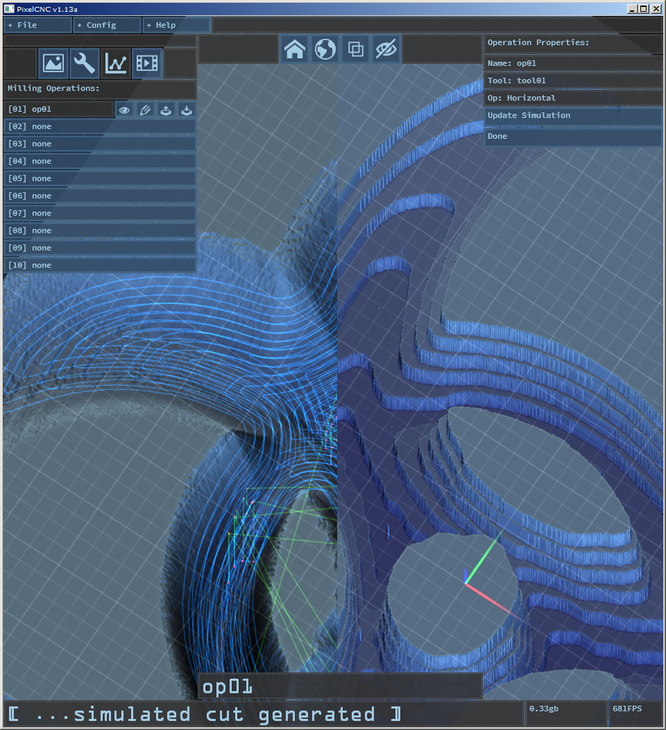
I *could* temporarily 'fix' the horizontal operation but it would involve stripping the existing sorting mechanism down (which is already sub-par as things stand) and runtimes would increase greatly as it would effectively order the cuts layer-by-layer, not moving on to the next cut depth increment until all cuts at the current level are complete. For some images with a lot of individual islands/pockets this means a lot of rapid movements between toolpaths. The ideal and optimal sort involves detecting when there are groups of cuts that form a pocket and linking them together so that the tool will effectively carve all the way to the bottom of a pocket when there are no other neighboring cuts to make. The existing sorting algorithm does this, somewhat, definitely not as much as I had hoped for but without it the toolpaths generated would result in many more rapids in most cases. Perhaps I could add in an option.

Personally, I'd rather not even touch it until after I've gone back to the drawing board and re-written the entire sorting algorithm from scratch. The individual cut moves themselves are solid, I just need a better way of linking them together, and it's tricky because they generate at depth increments across the whole image.

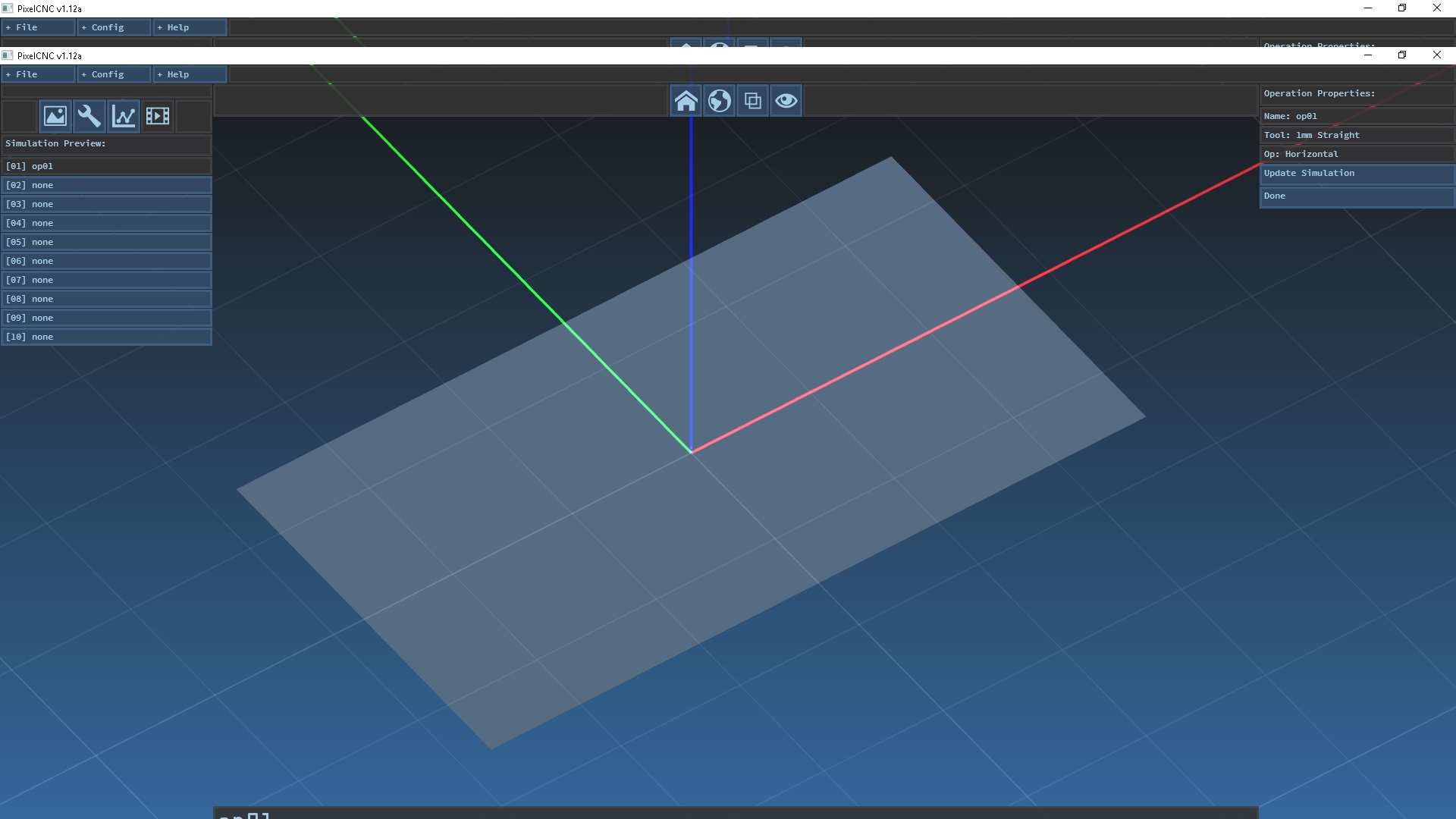
As for the simulation not generating I'm not exactly sure what the situation is, I don't have much to go on until you can give me more details. Is the horizontal operation generating a visible toolpath? If it is, have you tried lowing the mesh quality under the config menu in 'simulation settings'? What's the logfile have to say about the simulation generating?

Thanks!