
Indie game storeFree gamesFun gamesHorror games
Game developmentAssetsComics
SalesBundles
Jobs
TagsGame Engines

PixelCNC Has Moved: deftware.org

CAM software developed by artists for artists to create unique and original works on a 3-axis CNC router or mill. · By Deftware

Problem creating a tool path for the Tiger...

A topic by DenD created Apr 18, 2019 Views: 417 Replies: 8
Viewing posts 1 to 6

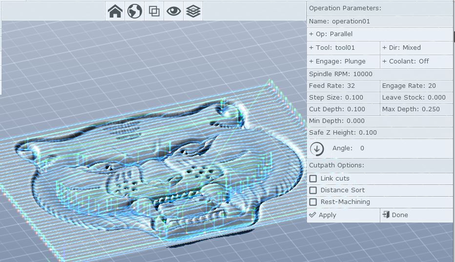
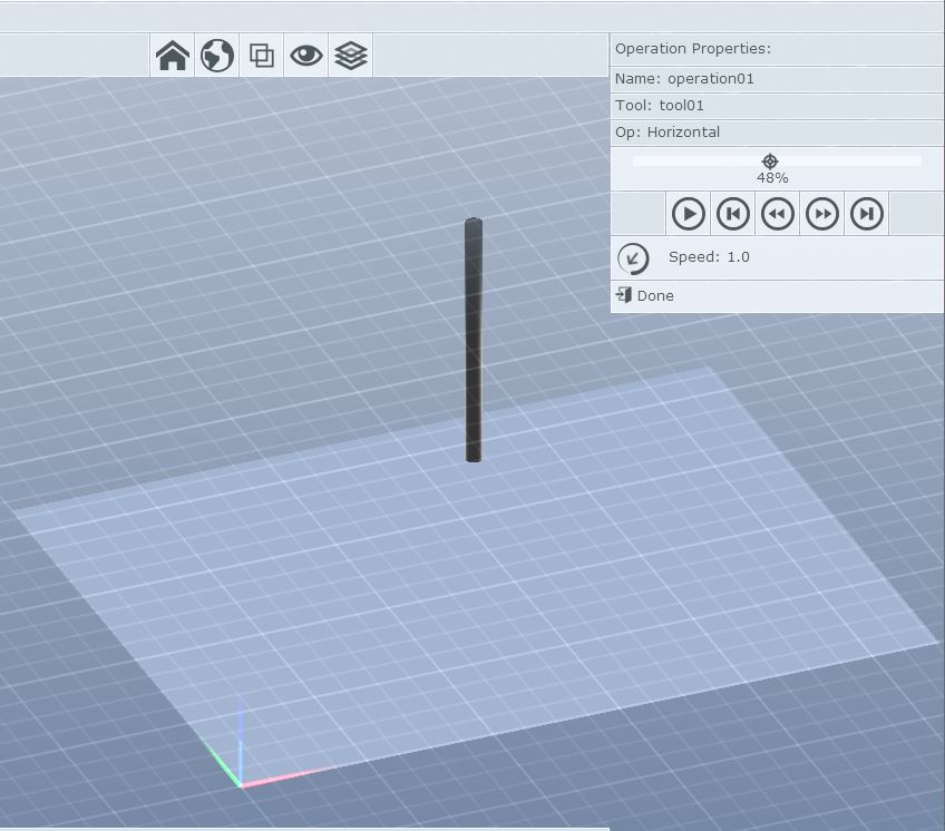
Hi, I have been dark for a while rebuilding my DIY CNC...  I returned to learn of a recent release.  After importing my Tiger image, creating two tools (BYW, it would be nice if there were a way to catalog tools permanently), I am not getting the results expected creating tool paths.  I have also gone from inches to metric back to inches (I don't know if there is any persistence kept for some values?).  Any way, I've left and created a new project, and this is my tool path screen...


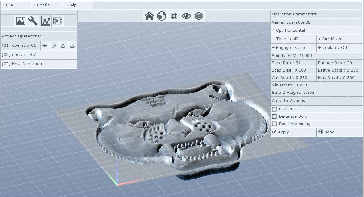
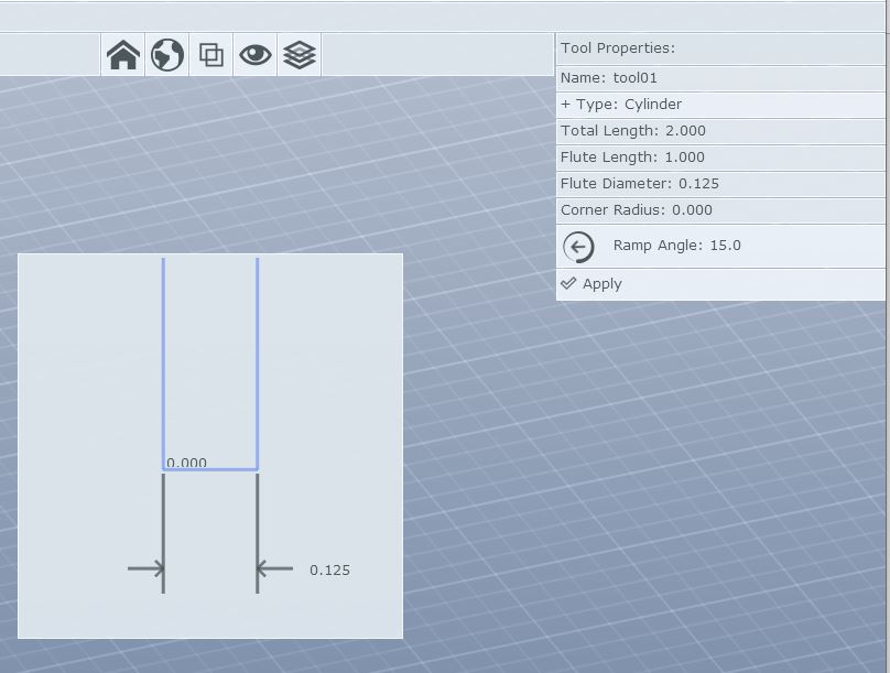
My Flat milling tool below...
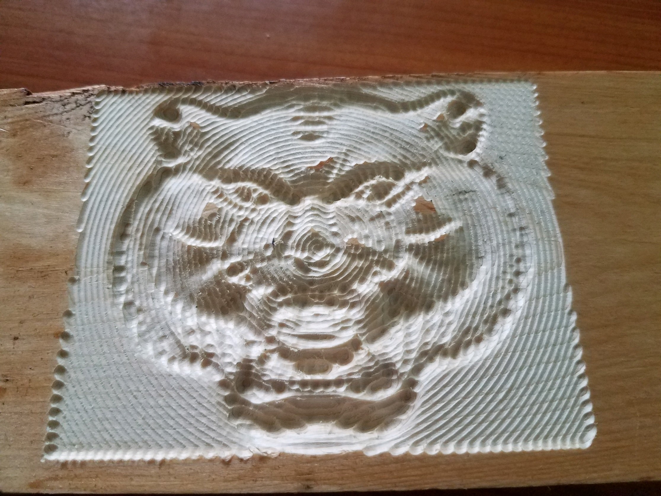
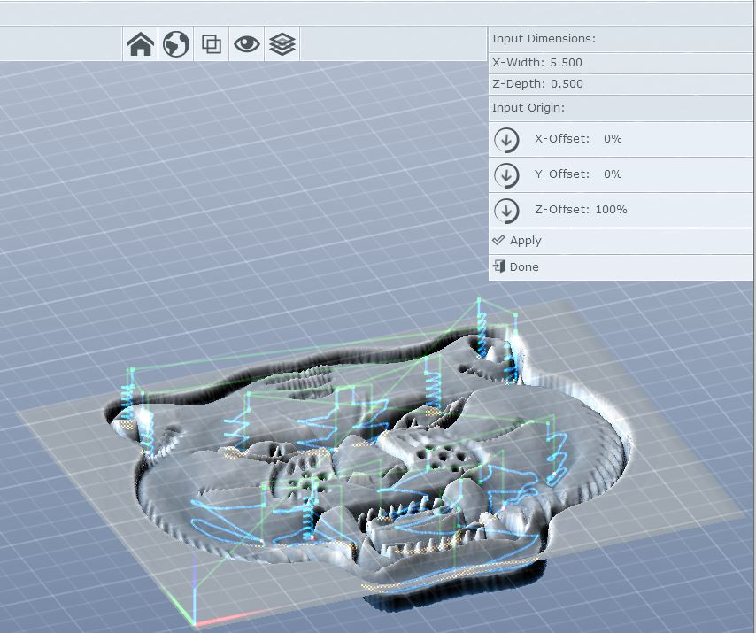


My image below...


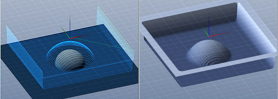
There is nothing to simulate?


When clicking generate G-Code the program abruptly disappears without a message...  What stupid thing am I doing wrong?

Thank you,

Developer

Hi, thanks for your questions. I see three things that will need changing: your leave-stock, cut depth, and min-depth are too large.

A quarter of an inch leave stock, for that particular project size and image means almost all of your project will leave nothing to be cut because the leave-stock effectively expands the project surface in all directions. If you have a perfect hemisphere,that is 0.5" in diameter, for example, and have a leave stock of 0.5" then the actual surface manifold which toolpaths will contour are limited to a 1" diameter hemisphere. The leave-stock imposes a margin in all axes, not just the Z axis. This way any vertical parts of the surface will also push the tool out away to ensure that there's stock left there. Start with a leave stock of zero just to get things working and increment it from there as you see fit.

Secondly, the cut depth is going to result in only two sets of horizontal cuts being generated. The horizontal milling operation generates sets of concentric cuts at 'cut depth' increments up to and including 'max depth'. So right now with 0.25" cut depth and project Z size of 0.5" it will try to generate cuts at the vertical middle of your project and then again at the bottom. The particular image you're using doesn't require much material to be removed as most of the features are all just below the top surface, with just a few pockets that actually go below 0.25", and with the 0.25" leave stock you had they pretty much just get removed entirely as cutting into the pockets would mean that 0.25" of stock isn't left in there between the cut and the surface your image produces.

The minimum depth parameter sets the depth-wise starting point for the cuts, relative to the top surface of your project (the max-depth similarly confines cuts to a maximum depth below the top surface). The minimum depth parameter functions as a cut-off point above which no cuts will be generated (except for engage/entry cuts), and with 0.25" you're preventing any cuts from generating in the top-half of your project. Set it to zero unless you have a reason down the road for cuts to be confined to the deeper parts of a project.

To help you get started I'm going to suggest trying a leave stock of 0.0, a cut depth of 0.1, and a min.depth of 0.0. Also, you might want to use a smaller step size, usually half your cutter diameter is perfect for horizontal operations. Start with that to get something happening and then play with changing different values here and there so you can get a feel for the way things are setup.

Not exactly sure why your simulation isn't showing anything - unless that's a screenshot from when there were no toolpaths generating (none are displaying so I imagine that to be the case).

Let me know how it goes!

 Charlie

Developer

I made up a little hemisphere example to illustrate the effect leave-stock has on an operation's toolpaths. This is a 1" diameter hemisphere with 0.25" leave stock:


It helped to re-watch the video again.  I made your recommendations... I can see the generated tool path now...  But the Program crashes attempting to write the gcode, I never get presented with a file location to save the file.  :(

These are the last messages to be logged..

223.080 backing up project...
223.080 op0 spawning cutmap generate job(862x683)
223.082 writing project headers...
223.084 r_modelnew = 13
223.084 writing image @2440...
223.085 >> r_end: reallocated 0.0mb model vertex buffer
223.086 >> r_end: reallocated 0.1mb model vertex buffer
223.087 >> r_end: reallocated 0.2mb model vertex buffer
223.088 >> r_end: reallocated 0.5mb model vertex buffer
223.089 r_modelnew = 14
223.090 >> r_end: reallocated 1.3mb model vertex buffer
223.109 >> compressed 444x352x4 rd444x352 to 130496 bytes
223.110 >> img_write: 444x352x4 (130496 bytes)
223.111 writing toolpaths @132948...
223.113 writing simimages @630172...
223.136 job_projgenopsimimage begin... (camop0)
223.137 cam_rasteroperation: rasterizing toolpath0 = 102 paths (24968 verts)
223.141 ...rasterization complete
223.142 convolving toolpath image(862x683) with tool profile(21x21)...
223.146 >> GPU image convolution img=(862,683) krnl=(21,21) ratio=0.648900
223.153 >> generated texture id 18
223.155 >> generated texture id 19
223.162 >> MAIN THREAD IDLING... (GL context in use by worker thread)
223.204 >> compressed 862x683x4 rd862x683 to 1649562 bytes
223.269 >> ...convo section drawn: -1.000000->1.000000
223.277 >> msg_realloc: reallocated to 2048.0kb buffer
223.281 >> msg_realloc: reallocated to 4096.0kb buffer
223.282 >> MAIN THREAD RESUMED... (GL context unlocked)
223.282 >> img_write: 862x683x4 (1649562 bytes)
223.283 >> 862x683 convolution complete (0.1370 elapsed)
223.289 project buffer = 2279766b...
223.291 ...operation01 simulation depthmap done generating

Developer

I'm not sure exactly what is causing the crash but I have a pretty good idea. The same thing was happening to another user so I've added some new code to a build that I'll be putting out today which includes many other fixes and changes. It has yet to be tested and I've never been able to re-create the problem myself on any of my test computers. Try going into CNC/CAM settings and selecting the post-processor you wish to use just before exporting G-code. Keep an eye out for v1.33a which I'm putting out in the next few hours here after I tie up some loose ends and it should be fixed, but you should also be able to get G-code export to work with a bit of persistence. Also, try saving your project after confirming your post-processor, before you export G-code.

Odd...  I wasn't convinced whether I was still considered within my Trial period or not?  I did pay for the use of this excellent program.  I read the rules about Trial versions... it stated I could not Save Projects.  So I saved my Project file.  Since saving the Project, I am able to write out gcode files.   Weird.

Developer

The free trial version has no time limit, but does not allow saving project files. If you have paid for the full version you own it now, which includes access to any future updates at no extra cost. Now that you've confirmed that saving the project prevents the export G-code crash I know that the fix I've put into v1.33a should work. I'm putting the finishing touches on v1.33a, mostly just updating the user guide, and then I'll be putting that out over the course of the day.

Feel free to share anything you create with PixelCNC that you carve on your machine!

Here is my 1st test...


Developer

Not bad! Now you just need to get in there with a small step size to clean it up :)