
Indie game storeFree gamesFun gamesHorror games
Game developmentAssetsComics
SalesBundles
Jobs
TagsGame Engines

Digital Logic Sim

​A minimalistic digital logic simulator · By Sebastian Lague

V2 is great it just needs some QOL upgrades.

A topic by LvlHedd created Apr 14, 2025 Views: 161 Replies: 2
Viewing posts 1 to 2
(1 edit)

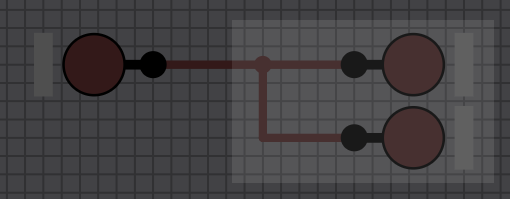
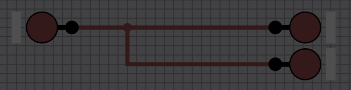
I'm super glad to have a grid snap ability now. I just wish we could toggle snapping to grid so I didn't have to hold CTRL constantly. In addition to this, being able to select wire vertices when selecting chips in a box grid could allow us to scale and move wires with chips without having to rewire them beyond a certain point.

Also a simple undo/redo or CTRL Z CTRL Y system would save me tons of time.

Please bring back toggling pin labels, only being able to select 'show on hover' or 'always show' makes for awkward organisation.

Now that pins are no longer locked to the side of the screen, the ability to rotate chips 90° and make square chips like CPUs would massively increase the varieties of chips available, this could be paired with the ability to decide which pin goes where on the chip when it is inserted somewhere else.

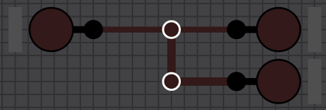
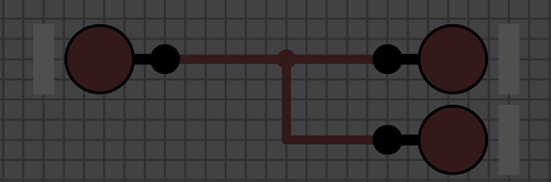
Pls make it so that cross-wire connections along wires count as vertices so we can move them independently.

Lastly, we still don't seem to have the ability to view segment displays on chips when they are place in circuits. The segment displays has also changed and has no negative sign, so the older tutorials make no sense and don't work for these.

I know it's lots of nitpicking but I just love the simple elegance of the program and want to see it reach it's full potential. Keel up the great work ! :)

Developer(+1)

Thanks for the feedback! If you add a display to a chip, you need to go to save>customize to set up how you want it to be shown. Regarding wire vertices, if I understand what you mean correctly, this is now possible in version 2.0.4 Otherwise could you elaborate on that?

(+1)

Thanks for the quick response :). Apologies, yes, the display-in-chip works thank you, I had not seen the option, now the only thing remaining about them are the missing negative signs (and the rearranged pin order but that's an easy solve by users to just rewire).

Regarding the wire vertices, this is pretty much what I had in mind, though that top middle handle does not allow for bisection of the main wire, just the movement of the attachment for the second wire along the first:


What I am mainly hoping for is for the white vertex circles to appear and be selected along with the pins and chips, so they may be moved together for organising large complex chips without having to manually shunt along each wire when a chip or pin is moved. See example:

Original layout:

Selection box:

Current outcome of move:

Desired outcome of move:

This wire layout would instead of being treated as 2 wires (IN 1 - OUT 1, wire attachment - OUT 2), be treated as 3 (IN 1 - Split, Split - OUT 1, Split - OUT 2)

This could be a toggleable option for people who want to move wires and chips simultaneously vs separately. Sorry if I've done a bad job explaining it... I'll be throwing another payment in as a thank you.