

(Note: If images are hard to see right-click and open in a new tab for full-resolution)
Intro: This tutorial demonstrates how to go about creating a work with sizable pockets that demand the removal of a relatively significant amount of material. This can be achieved using a single parallel operation with a workable depth of cut that results in multiple passes until a max depth is eventually reached at the bottom of the project - which is determined by it's Z dimension. In this case we're going to employ a larger cutter that can remove material more efficiently and in less time and then come in with a smaller tool to remove the remainder to produce the final product. Just about any operation can be used to perform the rough cut but we're going to use the 'horizontal milling' operation. This operation will remove material with horizontal cuts at fixed cut depths. Afterwards we will come in with a smaller ball nose cutter to remove the remaining material and bring out our desired form and detail in our workpiece.
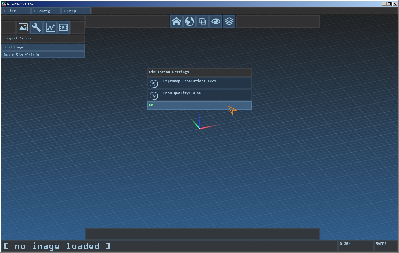
Simulation Setup: For this project we're going to want to see a fast approximation of what our generated toolpaths are going to cut like, so start out by changing the simulation settings to a depthmap resolution of [1024] and mesh quality of [.90]. You can use larger values if you wish but these values will keep the generation time down in exchange for faster simulated cut preview generation.
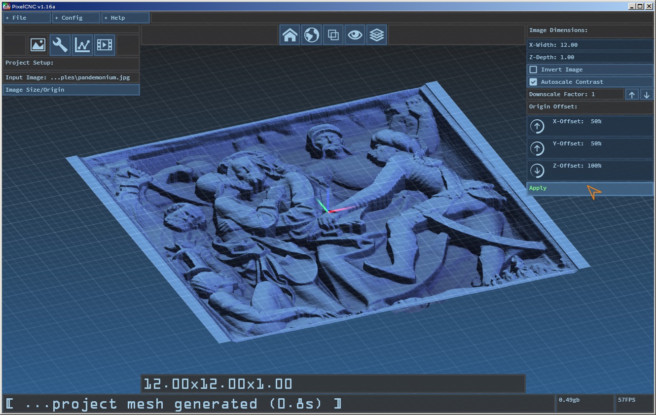
Project Setup: With a new project at the ready (File->New Project) click the 'Load Image' button and open 'pandemonium.jpg' from the included 'examples' folder in your PixelCNC folder. The image should load and generate a mesh in the 3D view. Click the 'Image Size/Origin' button to reveal the project's current dimensions and origin parameters. Set the project size/origin settings to a width of [12] inches and a depth of [1] inch. The 'Autoscale Contrast' option should be enabled here to ensure that the darkest shade and lightest shade from the image are considered the very bottom and very top of our project, respectively, even if they're not absolute black and absolute white. Set a 'downscale' factor of [1] to use the full resolution of the image. Then we'll use the top center of the project as our machine origin so our offsets should be X-Offset:[50%] Y-Offset:[50%] Z-Offset:[100%]. Once your parameters match the screenshot below press the 'Apply' button and the mesh will adapt its dimensions and position accordingly.
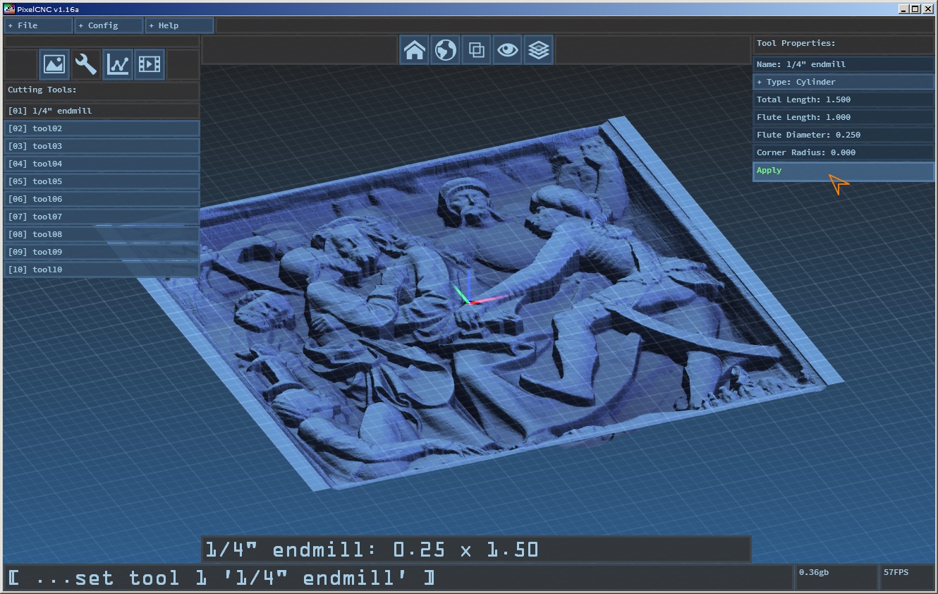
Cutting Tools: Next we're going to define our cutting tools. Click the wrench icon button to see the project's list of cutting tool definitions. For our horizontal roughing operation we're going to use a larger flat end mill. Click the first tool slot labeled [tool01]. The number in the brackets '01' is the tool index that the generated G-code will expect the physical tool to be in for CNC machines with automatic tool changing capability. For machines without automatic tool changing we will simply break up our operations into two G-code files at the end of this tutorial, one program for each tool.
Roughing Tool: In the tool definition parameters on the right side of the screen we can set the name of the tool to something more descriptive for readability purposes. I'll be changing it to [1/4" endmill]. Click the 'Type' button to select the [Cylinder] option. This will reveal the tool parameters necessary for defining a cylindrical cutting tool. For this tutorial we'll pretend that our tool has a length of 1.5" from the chuck to tip and as such set 'Total Length' to [1.5]. This is to keep the spindle chuck from crashing into the highest parts of our workpiece when cutting the deepest areas, at least with this project image. Our imaginary tool also has a flute length of [1] inches, a 'Flute Diameter' of [0.25], and since it's a flat endmill we'll set 'Corner Radius' to [0] inches. Now we hit 'Apply' to save these parameters to our tool.
Finishing Tool: At this point we can either create our roughing operation first and then come back and define our second tool and its finishing operation, or we can go ahead and define our finishing tool right now while we're here. This is entirely up to the user and their own preference. For this tutorial we'll just go ahead and create our finishing tool right now while we're here. So, click the second tool slot labeled [tool02] and we'll name this one [1/8" ballnose]. It is also a [Cylinder] type, and we'll say it also has a total length of [1.5] inches, a flute length of [1] inches, a flute diameter of [0.125] inches, and a corner radius of [0.063] inches - which is equal to the radius of the tool (rounded to the nearest thousandth) in order to yield a hemispherically rounded ball-nose tool profile. Press 'Apply' to save our finishing tool's definition.

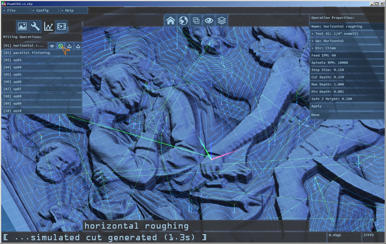
Operations: Now that we have both of the tools we need for our project we can move on to creating both of our machining operations. Click the line graph icon button to bring up the project operations. Click the first operation slot in the list on the left side of the screen labeled [op01]. This will bring up the operation definition on the right side of the screen, just as with the tool definitions editing mode. For this tutorial we'll change the name of the operation to [horizontal roughing]. Click the 'Tool' button and select our [1/4" endmill] we defined from the list. Click the next button, labeled 'Op' and select [Horizontal]. This will reveal the relevant parameters for defining a horizontal milling operation. We'll set the cutting direction to [Climb], which will create toolpaths that engage the tool with the material so that the clockwise rotation will scoop the material in the opposite direction that the tool is moving. This helps to preserve tool life by causing less rubbing than conventional milling.
Speeds & Feeds: For cutting 'speeds & feeds' you can use a special calculator to calculate these based on the capabilities of your machine. For those more experienced with CNC they will likely have evolved a sense of what speeds and feeds to use based on the material they're cutting, size of their cutter, number of flutes, depth of the cut, and capabilities of the machine they're working with. We'll assume that all the variables in play work out to a cutting feed rate of [60] inches per minute, and a tool rotation speed of [10000] rotations per minute. For a 2-flute cutter this comes out to a chip load of .012" being removed per tool revolution, which is perfectly acceptable for a 1/4" tool cutting most woods. If you have a hobby desktop machine with a router spindle such as the DeWalt DWP611, the minimum RPM is 16000 on the lowest dial speed setting. We can just scale up our feed rate accordingly. Our new feed rate for 16000 RPM is: 60IPM x 16000RPM / 10000RPM = 96IPM
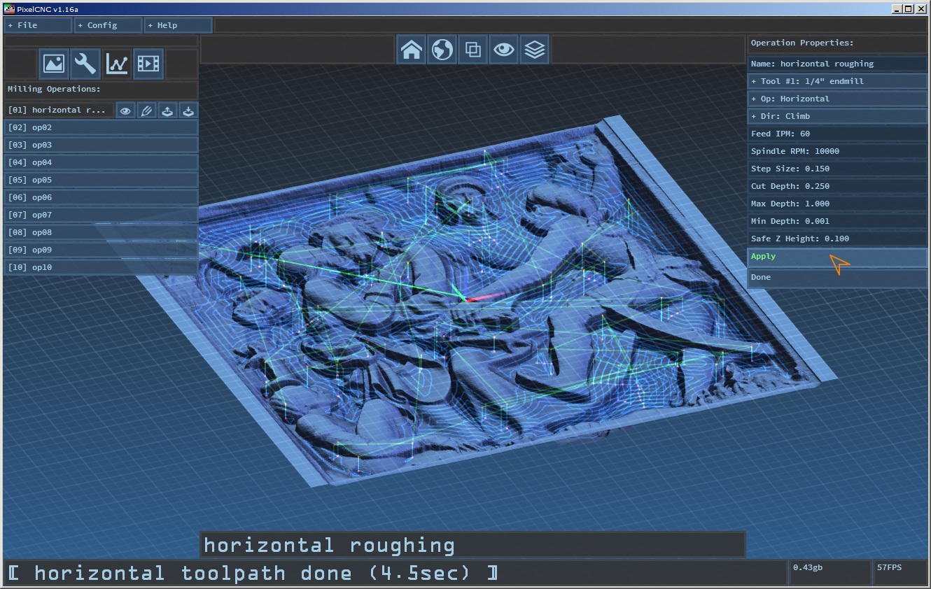
Step & Depth: Since this is our roughing operation we want to save time by moving a lot of material, fast, so we're going to set our 'Step Size' to just over half the diameter of our 1/4" cutter, and use [0.15] inches. We're going to cut the diameter of our cutter deep and use a 'Cut Depth' of [0.25] inches. The operation should be allowed to go as deep as our project image goes - the full 1.0" of our project's Z depth, so we set our 'Max Depth' to [1] inches. 'Min Depth' sets the high cutoff point where any cuts shallower than this depth are culled. For this tutorial we'll set it to [0.001] inches. Both the min/max depth values are relative to the top of the project, not absolute Z coordinate relative to the machine origin.
Safe Z: As long as our raw stock material is sufficiently flat we can allow our tool to move between cuts relatively low to the top surface. This minimizes total operation run time by reducing the amount of time that's spent traveling vertically when retracting from a completed cut and feeding into a new one. I almost always keep the 'Safe Z Height' at [0.1] inches unless I absolutely need to optimize for speed, at which point I'll get as low as ~0.025" but this is only in extremely specific situations. Once we have our horizontal roughing operation specified we can generate our toolpath by hitting 'Apply', just as we do with defining a tool.
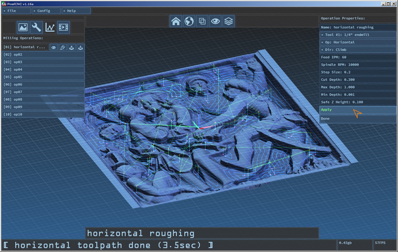
Adjustments: The horizontal operation is one of the slowest operations to generate a toolpath for and this is determined entirely by the depth of cut and step size. We can't really rely on having a larger step size to reduce the number of cut paths without causing some lone island spikes to form in tight corner features, which may or may not pose a problem, depending on the project. We can more realistically fiddle with the cut depth, however, but this depends on the machine and the material being cut. A less rigid machine might flex too much or not have a powerful enough spindle to handle to deep of a cut. These parameters should be tweaked to suit the machine that the code will be run on. Here's an example of changing the cut step size to [0.2] inches and the cut depth to [0.3] inches, you can see the reduced calculation time:
...However, this leaves more material for the finishing operation to come in and remove, which may or may not prove problematic, depending on the tool used. If a finishing cutter does not have long enough flutes it may not be able to cut high enough when at the bottom of a pocket to remove the larger remaining stock, or it may just as well overwhelm the machine depending on its rigidity and robustness.
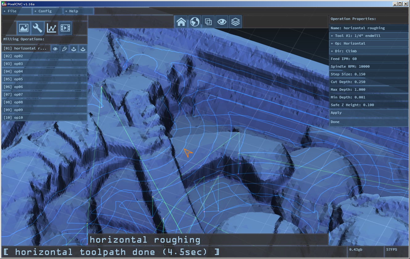
View Repositioning: Once we have a decent looking toolpath we can examine it visually by rotating the view around by click-dragging the left/right mouse buttons and spinning the mouse wheel to zoom in/out or click-dragging it to directly control the zoom. Pressing the home icon button on the view button bar top-center of the screen will return the view back to its default birds-eye vantage.
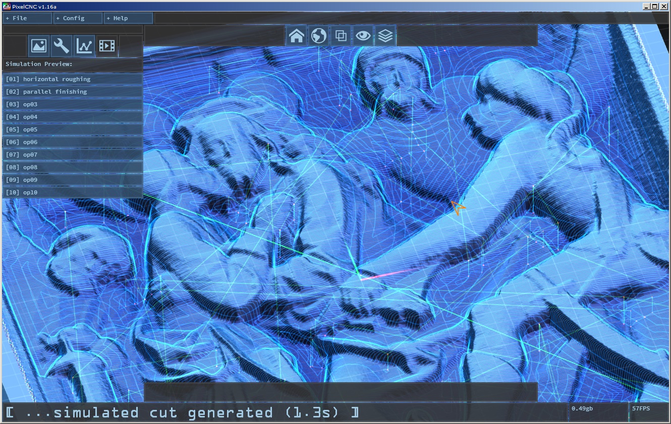
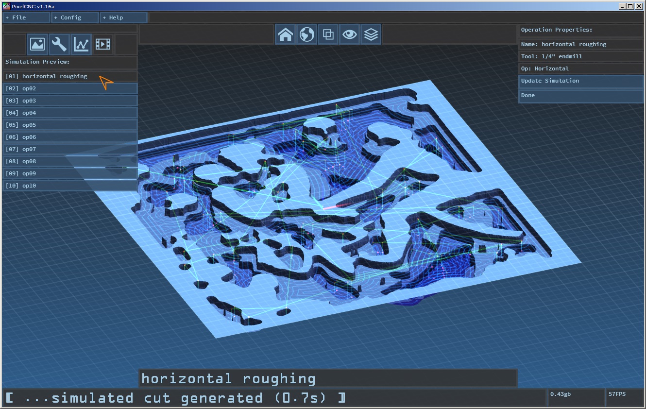
Simulation: We can get an even better idea of the cuts our toolpath will create on a CNC using the simulation preview mode by clicking the film play button. This mode also shows a list of the project's operations which can be clicked on to generate a simulated toolpath cut for users to examine and get a much clearer idea of what their parameters are going to physically produce:
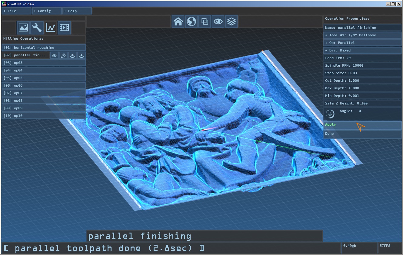
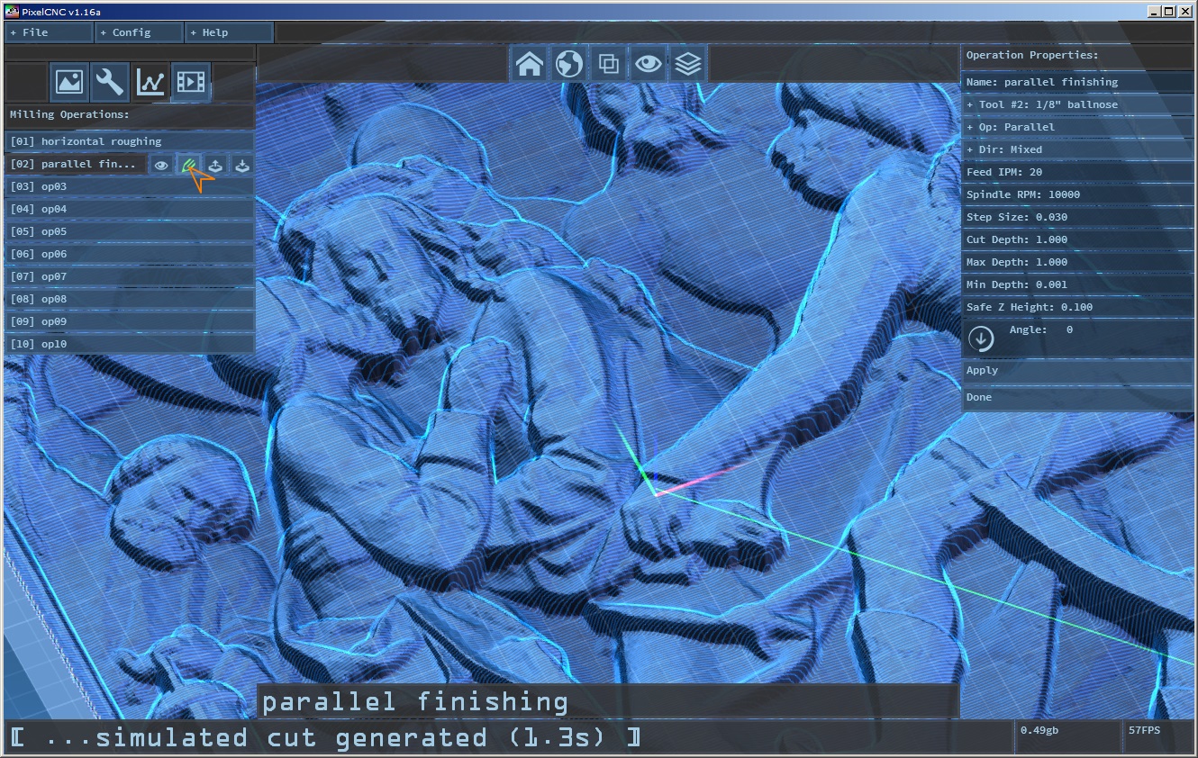
Finishing Operation: Once we're happy with our roughing operation we can go back into our operations mode via the line graph icon button and select the second blank operation slot. Here we can name the operation [parallel finishing]. We'll select our [1/8" ballnose] as the tool used, [Parallel] for our 'Op', and [Mixed] for our cutting 'Dir' so that the tool will cut in both directions in a zig-zag fashion instead of lifting up and rapiding to the opposite side to continue cutting in a single direction.
Speeds and Feeds: With the speeds and feeds it gets a little trickier here than with horizontal cuts being that our tool is going to be taking vertical plunge cuts almost half of the entire time the tool is engaged with the material in order to perform the 3D contouring cuts involved. This means that the center of the tool will be doing quite a bit of cutting. The center of a rotating tool is a very tiny radius that will be rotating. As such the flutes will be moving at a very low speed relative to the cut feed rate and the flutes on the circumference. We'll compensate by using a lower feed rate to give the tool tip a better chance at removing material. For our 1/8" ballnose tool, which we'll imagine has 3 flutes, we'll use a feed rate of [20] IPM and a spindle speed of [10000] RPM. This gives us a chip load of 3(flutes) x 20IPM / 10000RPM = .006" inches per revolution. We could go slower, or turn up our RPM, and the center of the tool will do an even better job of actually cutting. In the case of woods and plastics this isn't as much of a concern as it is with machining metals, so we'll call it good.
Step Size: For a finishing pass we need a tiny step size that will minimize the size of the 'scallops' between each cut pass, the little peaks along the midpoint between each cut path. For this tutorial we'll use just a little under 1/4 the diameter of our finishing tool, and set 'Step Size' to [0.03] inches. We want the tool to be able to travel from the top of the project workpiece to the bottom in one fluid cut so 'Cut Depth' should be the full Z depth of the project which also requires that our tool's flute length is at least this large so we'll set it to [1] inches (this is to prevent an operation from potentially cutting deeper than the tool is capable of but this will be changed in the future).
Confinement: 'Max Depth' obviously should be the full project depth, [1] inches, and we can re-use a 'Min Depth' of [0.001] inches which will leave the very top most surface of the project untouched on the left/right sides bordering the project. We could reduce 'Safe Z Height' but we'll keep that at [0.1] as well. For fun you can play with the 'Angle' value and modify the direction of the cuts, but for this tutorial we'll leave it at [0] degrees. Click 'Apply' and the toolpath will generate and it should complete a bit quicker than the horizontal roughing operation we created due to the simpler nature of the toolpath.
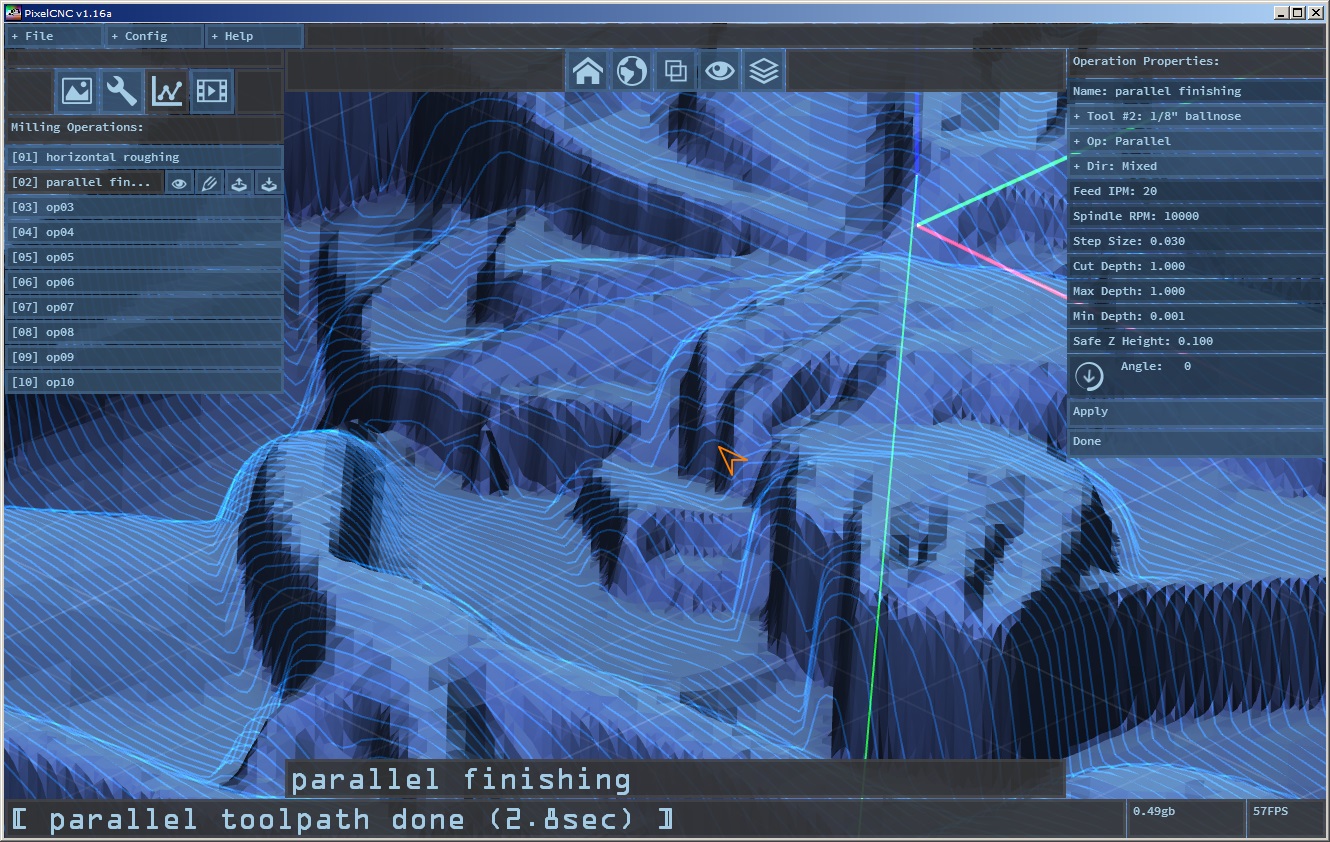
Once we have a toolpath we can examine it more closely by moving the view around.
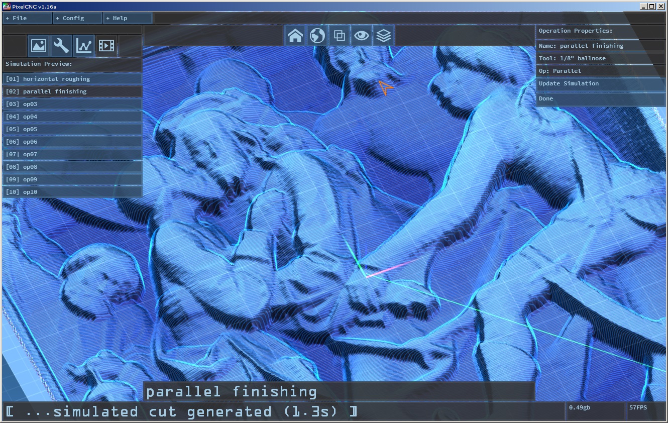
..and again we can go into simulation preview and click our [parallel finishing] operation to generate a preview that is the culmination of both the roughing pass and finishing pass. Granted in this situation the parallel finishing operation will look identical whether or not the horizontal pass is present but in reality, on a machine, the tool or machine might not be so cooperative removing all that material with the tool making so much vertical plunge cut motions through so much material.
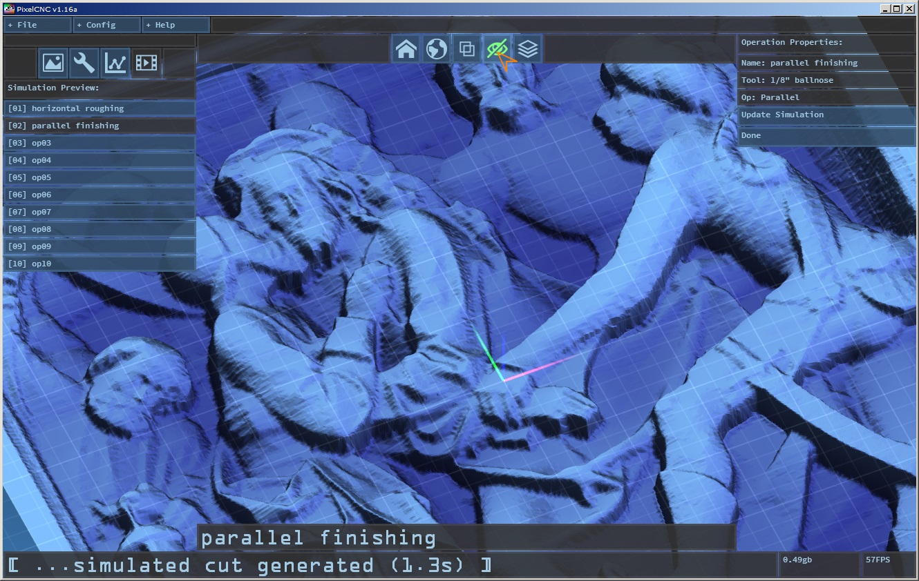
Toolpaths can be hidden by clicking the visibility eye icon button on the top center button bar to toggle drawing of any toolpaths, this especially helps with viewing simulations where dense toolpaths are in play:
Exporting Separate CNC Programs:
If we go back into operation editing mode by clicking the line graph icon button we have a few buttons for each individual operation. There's four buttons that appear on an operation in the operations list when they are selected for editing.
The eye icon toggles visibility of that operation's toolpath, and only applies if the global toolpath visibility toggle isn't already hiding rendering of all toolpaths The pencil icon toggles whether or not the G-code for the operation will be included in exported G-code as well as a generated simulation preview. The up/down arrows allow re-arranging of the order that operations are in.
If we want to export each operation separately we can start by clicking the pencil icon on our parallel finishing operation to prevent it from being included when we export G-code. Now we can export our roughing pass G-code by clicking the 'File' menu and clicking 'Export G-Code'. A file save dialog lets you navigate where you wish to save your CNC program code, with a name like "tutorial_roughing.nc".
Now we can disable writing of our horizontal roughing operation to G-code and re-enable writing of G-code on our parallel finishing operation and repeat the G-code export steps, being sure to save to a different file name, such as "tutorial_finishing.nc".
The End :)