Indie game storeFree gamesFun gamesHorror games
Game developmentAssetsComics
SalesBundles
Jobs
Tags

I don't take any part of your reply to be insulting, no worries there. I'll start off with something to think about - not every CNC machine cuts.

So, for scenario B with the zone modified feed rate, the tool in this case being a pen (or a laser with fixed output level, or an air brush with a fixed nozzle size and flow rate) would leave less ink (or the laser would burn not so deep/dark, air brush would leave less paint, etc). This absolutely could be accomplished with multiple overlapping tool paths creating the different levels of the gradient, but that also increases the run time of all the tool paths and goes over the same ground multiple times. But if a zone feed rate (zone gradient effect?) were implemented similar to your spiral operation (with the center being user defined, along with # of rings, eccentric VS concentric) the toolpath would go faster the farther from center the tool got. This could have an interesting effect on a crosshatching texture, too.  See the attached picture of a test piece I did. It's an attempt at Bender on canvas using Sharpies. Sharpies and canvas don't mix well, even if the pen holder is spring loaded - the canvas chews up the tip rather quickly. The gradient effect would work quite well on the stripes, but could also be useful to force focus in a particular spot. I realize after writing all of this that it's a request for a niche function few people might use.

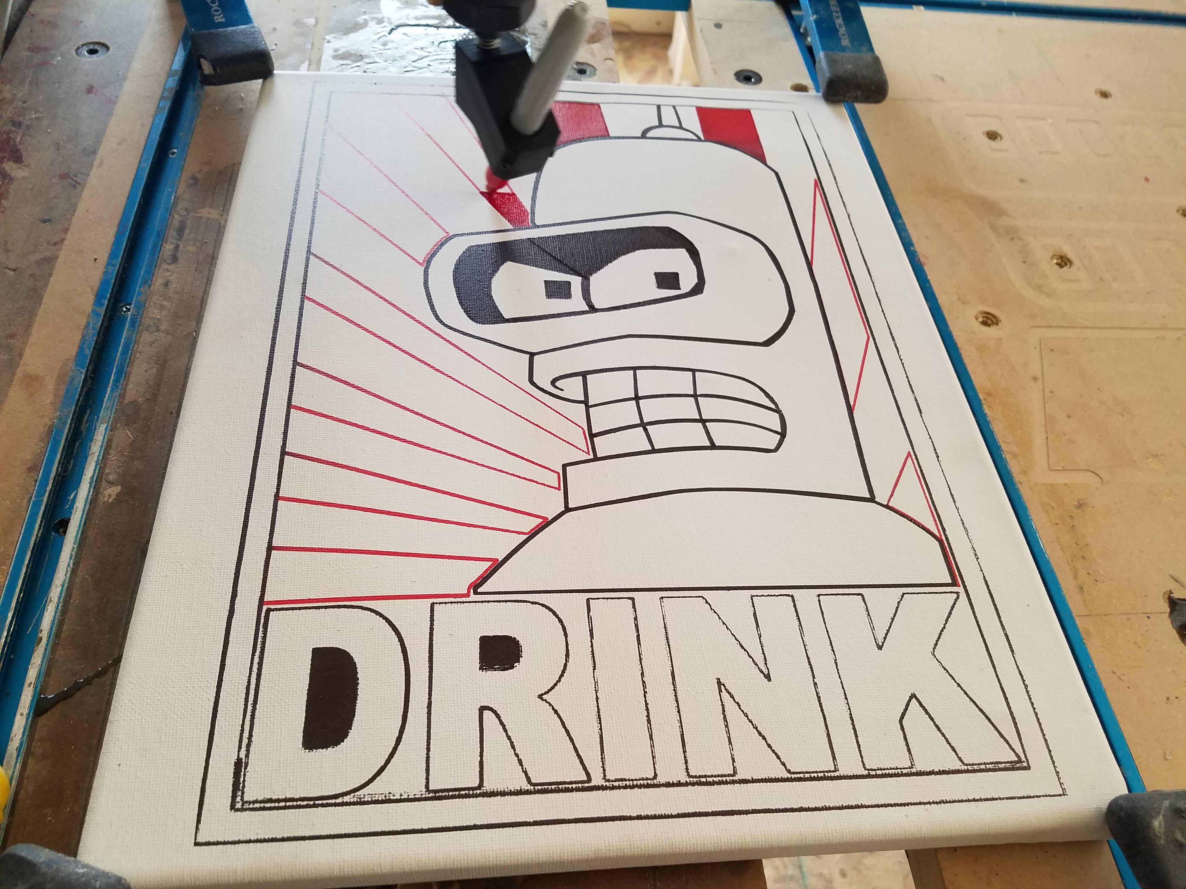
As for dynamically controlling spindle speed - that sounds like a good complimentary feature for trochoidal milling.

The scenario A function that I described is essentially a finishing cut pass. In a discussion about another piece of software used for cabinets, objects that were below a certain size had the option of having the last pass slow to a specific feed rate in an attempt to not damage or eject the piece.  I imagine the use of either spiral upcut or downcut bits combined with not babysitting the machine because it's not cost effective in a production shop, having the machine slowdown on the last pass cuts down on tear out or projectile ejection. For the interior of pockets, spiraling the tool all the way to desired depth inside the pocket profile at a slow steady descent  usually works as long as the piece in the center doesn't cause tear out when milled away. While cutting a piece of aluminum for a Jeep switch face plate, one of the slugs from a switch hole got caught on the bit just before it was completely cut free and it ended up pulling the whole piece up and into the bit (of course it was the part that was farthest from any of the 6 bolts holding the stock down). Had I either manually slowed the feed rate down, or the toolpath generator auto-magically applied the size less than X @ last pass rule on the switch holes, the slug probably would have been cut free without damaging the main piece.

Ah, I knew I had to be missing something! It's an interesting idea for sure. Have you tried doing it with the image itself? I don't know what exactly you're doing to produce toolpaths that are almost exclusively level, other than perhaps setting project Z depth to a very tiny size and pretending that's your cut depth for the Sharpie to traverse. If you took your image for the stripes and added a radial gradient to them and toolpathed off that using the contour-carving type operations (i.e. parallel, spiral, etc) then you could get the Sharpie to be lifted off more, or have less pressure, at either end of them. That likely won't be as good as changing the feed rate though.

I'll have to think about that because there's a lot of different ways to go about something like that. For instance, would you want to set a percentage of feed rate change per inch of depth/step-over? Or would you just want to say "at this point we feed at this rate" and then pick a distance point "at this distance and beyond we're at this feed rate". That would allow at least a feed rate gradient based on radial proximity to the original center point.There's really a huge array of possibilities, you could also have a set of points all over the project that are blendpoints for different feed rates, or have square/diamond/star shaped concentric zones of either blending between feeds or sharply stepping between them.

Then would you just want a linear transition from one feed to another or something more like a polynomial transition that gives a different dynamic? You could have plain old linear, but maybe something like an ease-in or ease-out cubic transition would be better. Maybe the user should just have control over the curve's start/end derivatives to change the feed rate blend dynamic.

There could even be a new marker/pen tool that just doodles on the project material surface. That might be neato too.

Well I'm not going to make any promises just yet, but I'll definitely keep a location-based variable feed rate idea cooking in the back of my mind, because there is definitely some value there as a feature for manipulating the final appearance of something. I think it could be one and the same with the variable feed system for maintaining a relatively constant spindle load - spawning visible points across the project for an operation which affect the feed rate as the tool approaches them. We will see! This is something that I probably won't be able to get around to until at least 6 months from now, or more, depending on how things go with the features currently lined up for me to knock out. In the meantime feel free to keep sharing your work here for other users to see. It's a pretty cool use case for PixelCNC!

Thanks,

Charlie

I treat the Sharpie's similar to a drag knife . Disable the spindle, set Z to top of material, define depth of cut for the pen at .05", and set profile or pocket toolpaths to .05". There's a 2.5D function in VCarve called fluting that will perform a ramped cut over the length of a profile, and it has options  for:  

  • start depth and final depth of cut
  • tool type
  • to make the flute have a linear ramp, to ramp at start,  to ramp at start and end (think bowl/concave shaped), to ramp for a fixed length
  • to define the ramp as a linear motion or as a smooth motion (similar to cutting a pocket with a radius end mill VS flat end mill)

Because I was focused on just the flat drawing at the time, I hadn't thought about applying this to the Z axis (or even an A or B axis for rotary jobs), but it makes sense - merging the two scenarios that I originally wrote about as it boils down to modifying the feed rate (or spindle rate) based on possible parameters:

  • distance to/from Z coordinate
  • distance to/from X-Y coordinates
  • distance to/from A-B coordinate (tricky if you allow your rotary to spin more than 360 degrees)
  • spindle speed target = ST; spindle speed actual = SA; adjust feed rate by F%, adjust spindle rate by R%

As for implementing the gradient function or better yet, the radial modifier, I think that a simple linear percentage as you move between zones would give the best performance. I imagine that having more than one modifying layer could be tricky, do you default to the lowest value, the highest value, or a value between the two?

I know you can't or shouldn't make promises - this is only a suggestion based on an idea I had from a recent project.  I can probably achieve a similar effect from having multiple overlapping toolpaths at different feed rates... I'll end up making a tool holder/mount that holds a modified fountain brush with an air line that keeps the reservoir  pressurized.  The trick will be to either hand edit the G-code to pulse a solenoid for semi-constant air pressure, or to find a way to have a post processor insert an M-code based on the distance traveled when the tool/brush is in use. Or just sit and watch it and make sure the ink doesn't run out or spit all over the project. It would probably be easier to just to paint the damn thing by hand... if I could paint.