Indie game storeFree gamesFun gamesHorror games
Game developmentAssetsComics
SalesBundles
Jobs
Tags

PixelCNC Has Moved: deftware.org

CAM software developed by artists for artists to create unique and original works on a 3-axis CNC router or mill. · By Deftware

Engraving Text

A topic by DJL54 created Jan 09, 2023 Views: 191 Replies: 4
Viewing posts 1 to 3
(1 edit)

Hi Charlie,

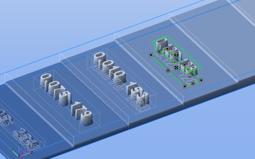
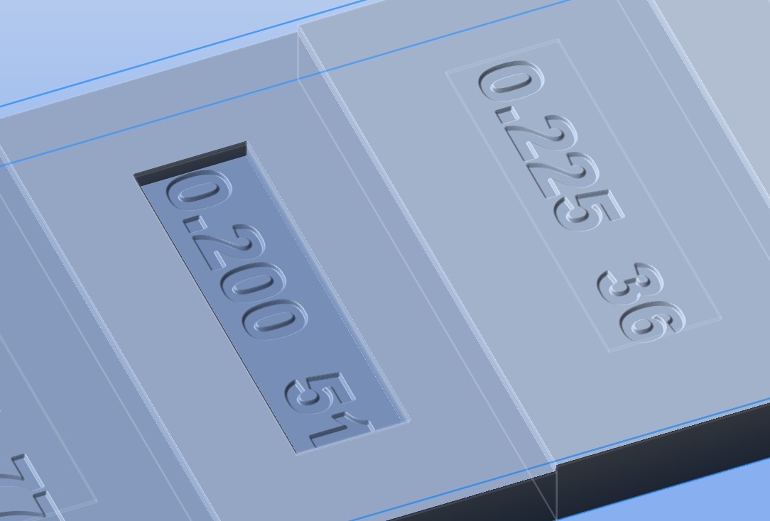
I would like to engrave text on the surface of raster layers at different levels.  I have created each level as a separate Raster Layer and then placed text on  the surface.  What I want to do is engrave the text 0.010 deep into the raster layer.  I create the Text Layer and Trace Text to Paths and then use this Paths Layer for the Project Operations.  The way I have been able to make it work is to use the Medial Axis Carving and play around with the Depth Offset to get close to what I want.   Being Medial Axis Carving the depth of the text varies (as it should) but this not what I am trying to achieve.  Is there a way to get a Paths Layer of test as a single line font and then use either Paths Carving or 2D Profile Milling to engrave the text.  Right now if I use the Paths Carving or 2D Profile Milling the tool path is at the top of the Canvas instead of the top of the Raster Layer and I can't figure out how to get it to cut into the top of the Raster Layer.  In all cases the text on the Paths Layer ends up as a two line font as it is derived from the Text Layer.  So after all the verbiage above my end goal would be to have a single line font that I can engrave with a v-bit on the top of each Raster Layer.    If this is not possible I think (haven't tried it yet) I could leave the text raised by 0.010, combine all the layers and do a Parallel Carving Operation with a v-bit with a small step over - just would take a long time. Screenshot attached.

Thank you 

Doug

Developer

Hi Doug,

You can offset lower where the medial-axis carving operation will cut with the Depth Offset parameter that shows under the Medial-Axis Carving Operations toward the bottom of the operation parameters. A positive value will offset downward, where zero represents the top of the canvas, so you might have to calculate what offset to use. When your mouse is in the 3D view you can put the cursor on the point of the canvas you want to get the Z coordinate of by looking at the coordinate readout on the status bar at the bottom of the PixelCNC window. Just subtract that value from whatever the Z coordinate is for the top-plane of the canvas. If your machine origin is set to the top of your canvas then you just use that number, except flipped positive (because all coordinates on the canvas surface, with the origin set to the top-plane of the canvas, will be less than zero). That will put your medial-axis carving cutpaths where you want them! Rapids will stay at the Rapid Height above the top of the canvas though, regardless of your Depth Offset.

Just as an FYI you can also composite your text onto your canvas subtractively to get a better visual representation of what you're trying to do. For actually generating cutpaths I would do like you already are and trace the text to paths to use as contour input for the operation, or just have the layer groups with each text-layer inverted and Z-Fill set to the top of the canvas, which seems a bit more roundabout though but it will do the same thing.

 - Charlie

(+1)

Hi Charlie,

Still having issues with this file.  Bit of a change in plans as I could not get the text Trace to Paths to work.  I think I have set up the Text Layers incorrectly  so just gong to use Blend = Subtractive and use a ball nose bit to carve out the text. My work flow is as follows:

  1. Create a Canvas 9 X 2 X 0.25
  2. Create the stepped “profile” by creating a Raster Layer for each section with the Origin at 0.0 and the Z-Size the height that I want each section to be – eg 0.050, 0.075, 0.100 and so on.
  3. Create a Text Layer for each corresponding Raster Layer.  I want the text to be 0.010 deep so I tried making the Text Layer with a Z-Size of 0.010 with the Origin 0.010 below the top of the corresponding Raster Layer.  Using Subtractive this makes the entire Text Layer lower than the top of the Raster Layer and the actual text lower more.  See TextLayer 0.200 in the attached image
    1. Top of Raster Layer -0.050
    2. Top of Text Layer -0.100
    3. Topo of actual text -0.110
  4. I thought the Top of the Text layer and the Raster Layer would be the same?  The only way I can get the Top of the Text Layer and the top of the Raster Layer to be at the same Z-height is to make the Z-Origin 0.24 for all the Text Layers.  Is this what I should be doing or have I gone totally off the rails.

Thought I had Layer Groups figured out.  I have all the layers in Group 1 and the Text Layers also in Group 2.  Selecting Group 1 shows everything as expected.  Selecting Group 2 shows the boundaries of the text layers but no text?  When I go to Project Operations and select Group 2 nothing shows?  What have I done wrong?

I want to do a clearing pass with a 0.25 bit then a final pass with just the text.  This does not work with Group 2 so I use Group 1 (all layers).  REST Machining is turned on so just the text should get carved but passes are also made at each change of height.  Leave Stock is set to 0.001 to ignore some “artifacts” that show up on the flat surfaces.  Once again where have I gone astray?

I wanted to attach my file but don't see how to do it in a Reply?

As always any and all suggestions very much appreciated.

Thank you

Doug

Developer

Hi Doug,

The best way to use the Trace to Paths function on an individual layer is to hide everything else first and just have the layer by itself. The green/red Z-contouring plane that the function shows is only really true and accurate when tracing the canvas to paths as a whole. When tracing individual layers it can be a bit deceptive because it doesn't take into consideration how the layer is being composited with the canvas, per its blend mode, and the tracing plane may not accurately depict what will actually be traced.

To make a text-layer that subtracts a certain depth you only need to make it's height the depth you want it to be and then move it up beneath the top of the canvas by the same depth. i.e. for 0.1" deep text you would make your text-layer's Z size 0.1", and if your canvas' Z size is 0.5" inches then you would set your text-layer's Z origin to 0.4". Then set the text-layer's blend mode to subtractive. This applies regardless of what is below the text-layer and how high it is. So, each 'step' in your project would basically have the same layer Z origin and Z size with only different text and XY position. 

If the text-layers are subtractively blended with the canvas, and they are the only things in a group (with the canvas' Z-fill set to the bottom of the canvas) then you will not see anything when that layer group is active. In order for the text to show it will need a different blend mode, or the canvas Z-fill to be set to the top of the canvas (not the layer's Z-fill as shown on the layer's properties, but the Z-fill under Canvas Properties).

If you want the text to blend the way you were originally trying you can invert the text-layer and set its Z-fill to the top of the canvas, and set its blend mode to Minimum. This will allow you to set the Z origin of the text-layer to the exact Z coordinate you want the text to be cut down to. The top of the layer (i.e. Z origin + Z size) will need to be at least as high as the surrounding material the text will be cut into.

I think you should be able to get the text Trace to Paths to work and then can use the medial-axis carving operation using a Depth Offset down to the material depth you want to cut into. There's no way to directly convert text or anything else into single paths to use with the paths-carving operation, unfortunately. The closest thing would be a function that calculates a medial-axis path but that will leave all sorts of extraneous paths on there at corners and stuff. It won't directly generate 3 lines for the letter 'H', for instance.

If you switch your text-layers to use the minimum blend like I mentioned above, you should be able to toolpath Group 2 if it only contains text-layers that are set up that way, but you will still need to set your Canvas Properties' Z-fill to the top of the canvas first, then you will be left with the text as pockets that you can generate toolpaths from.

I will do up an example project you can look at and email it back to you later today :)

 - Charlie