
Indie game storeFree gamesFun gamesHorror games
Game developmentAssetsComics
SalesBundles
Jobs
TagsGame Engines

Digital Logic Sim

​A minimalistic digital logic simulator · By Sebastian Lague

DDR-REG

A topic by Windows7601 created 35 days ago Views: 148 Replies: 2
Viewing posts 1 to 3
(1 edit) (+1)

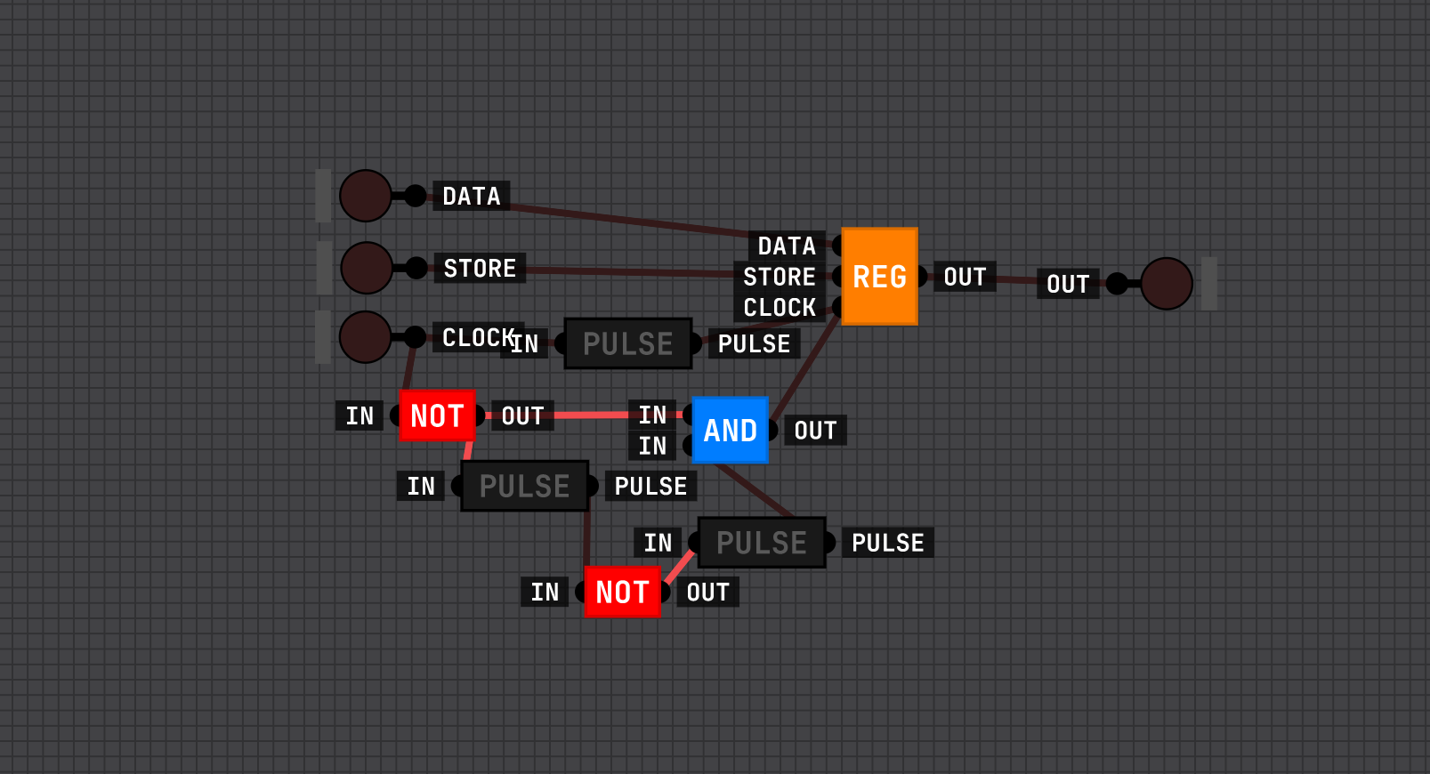
By using a delayed NOT pulse, I managed to make a DDR (Double Data Rate) register.

The only change from the outside compared to the regular register is that it also saves on the falling edge of the clock. It uses a delayed NOT pulse (CLOCK => NOT => PULSE => NOT => PULSE => AND with CLOCK => NOT => AND with AND => REG-CLOCK). The DATA and STORE signals were not changed, but a PULSE was added to the regular CLOCK signal because without it, enabling both STORE and CLOCK would just cause the output to be synced with DATA.

This is a big leap for me, so now I can put DDR registers into my custom CPU, which I'm still figuring out the ALU (multiply and divide part) for.

What do you think?

PHOTO:


In the same day, I used the bus feature to make a full fledged 128bit DDR RAM. I call this DLSDDR1 technology for some reason XD

(1 edit)

Interesting. A delayed pulse was precisely what I have been missing. I'm planning to make my own working Tic-Tac-Toe in DLS (maybe even a TTT bot), and it would have been near impossible without any form of delay. In my case, I did the normal pulse delay (in -> pulse -> not -> pulse -> out). putting a not behind the first pulse will make it pulse when the input is turned off instead of on.