
Gotcha, I'll keep an eye on them :) Thank you!
It's a bodge to say the least, and I have no clue if I named things correctly since I have no electical engineering knowledge at all, so don't get your hopes up lol
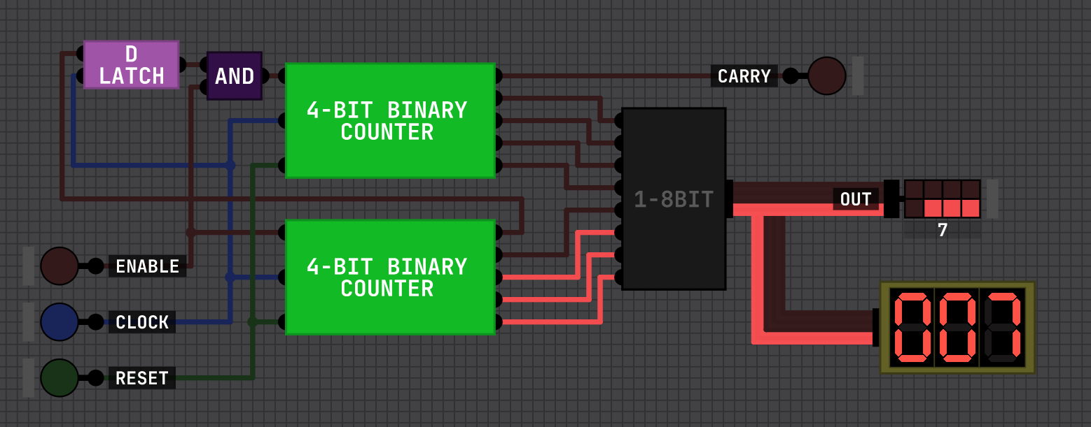
This is the inside of the 8-bit counter. The 7-segment display stuff is taken straight from Sebastian's videos. The latch is just there to make sure that the second 4-bit counter only increments once the carry bit and the enable signal are high.
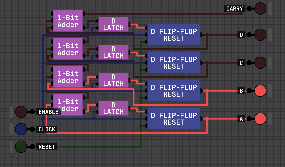
This is the inside of the 4-bit counters. I based it (to the best of my ability) on a 4-bit shift register, and then added the adders to make it count in binary instead of just shifting each bit up the chain. (I realised while writing this that I didn't need the d-latches in between the adders and flip-flops, so I removed them. I just can't be assed with taking a new screenshot lol)
I honestly have no idea if the flip-flops do what they're supposed to, since they don't really flip-flop, but I didn't understand any of the articles or posts I was reading, nor did the schematics translate well when I transfered them 1-to-1 into DLS so I just made do with what I had.
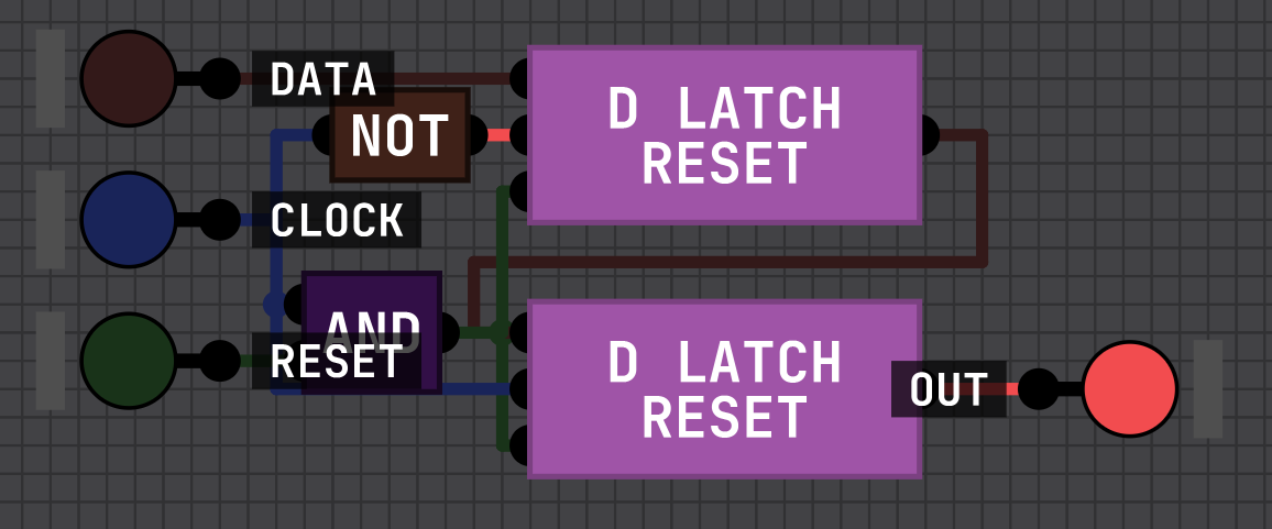
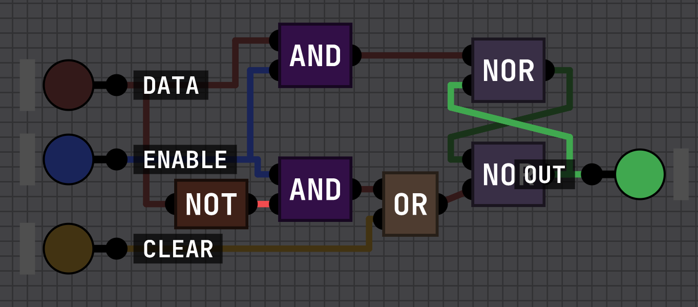
These are the flip-flop followed by the latch in case you were curious. :)