To create a bit group hover over where you add inputs/outputs and press '+' or '-' which will add an input to the group. Also, I agree the vertical bus line visuals would be nice.
What I mean exactly by "bit group" is to have one single input which represents multiple single-bit input, and then you will be able to connect this bit group to another input with the same number of bits using one single line (some some of bus). I hope it is more clear now.
From a higher level component you see the "8-bit" input as a single "dot", and then you can connect it to other "8-bit" inputs as one line, without having to explicitly map all underlying connection. then it will look like a "bus". In the lower-level components then you will have the option to "expand" the 8-bit input into discrete bits to work with them individually if need be. Hope that makes more sense now.
Very strange. The loading screen flashes on and off but doesnt load. In task manager, it appears for 5 seconds then closes. If any one has any ideas, would love to get this working! Thanks.
A way to transfer projects from a current version to a newer version of the simulator.
A way to remove and move inputs/outputs.
A way to share projects.
A way to have multiple workspaces for one project. For example there could be tabs at the top and like one workspace I could be working on one thing and in another I could be working on something else.
Expandable work area for big projects.
Things that would just be nice:
Having it as a proper application. I mean like you could give it its own installer and it could be in the start menu. Stuff like that.
If you could do all these things that would be wonderful.
AWESOME. I do have a few suggestions. First, i think that being able to right click and delete a wire will be cool because i dont like reaching to delete XD. I think also trying to implement a way to put a block into a wire (image below) and making it connect would be cash money.
Hey guys, i thought this was a cool idea. In his second video about this, he said we need a clock to let us know when to store data. Well this is my idea of getting a clock in the sim. If we make REGISTER B always 1, and REGISTER A (0) at the start, we have a clock with 4 varying speeds.
I tried way too many different ways to get this clock to work, and i'm sad that I used 2 hours of my time when the answer was as simple as adding a NOT gate.
The reason the NOT gate is connected is the sim has a hard time running logic to something if its not connected with an input, but it works.
My original idea was a pin that is a kind of a push button (monostable instead of bistable) so you could pulse mechanism with one mouse press instead of two
(also sorry for late reply, but notification system refused to notify my about replies)
This is totally awesome, and definately has the potential to be one of the best logic simulators out there (especially as it's free).
A few suggestions (to help you make it the best):
-A way to snap wires to go either vertical or horizontal, maybe by pressing ctrl.
- A way to edit and delete chips you made previously.
- Some way to get more space such as zooming or moving the work area.
- A way to group wires and inputs into a single wire or bus line.
- A decimal representation of negative numbers.
- Moving the mouse over a chip input shows the input name.
Also there is no decimal representation of outputs, and the input names don't show.
Something else that might be interesting is adding a simulation rate to slow down the speed like you demonstrated in the "How do computers remember" video.
I'm excited to see where this project goes. Keep up the good work.
hey man, i love your program. I have a suggestion I think you should add to the list of request (sorry) is a way to get the binary output in numbers, like you have in your second screen shot [the one with the ALU].
also maybe add hover text to the nodes? cause when i create a chip, like the alu, the next day I might not remember which node is the carry, negative, and zero nodes.
Well I've got myself a new addiction... I made an addressable 4-bit register, first time I clicked Create it didn't work so I rebuilt it and it worked somehow. Amazing software :)
Suggestion (that I haven't yet seen): allowing to increase the height of the chip bar, instead of having to scroll
A 7-segment would also be lovely, but I understand that'd require quite the rewrite especially if inside circuits :p
EDIT: I managed to build a 6 bit x 6 bit multiplier, with 12-bit output, made with no less than 11 4-bit binary adders and a mess of wires :D
I found a bug where I have the two ghost pins that don't work and can't be deleted or changed but for some reason this only effects the project I use the most.
Not yet, but I do plan to add a chip editing feature. Just need to figure out the details with what happens in places where the chip has been used, and now after editing potentially has more/fewer inputs or outputs.
i don't know how to make games, so take this with a grain of salt.
what if you had a refresh button. when clicked the system takes a moment and numbers all the wires, inputs, and outputs. After doing so it sets a 3rd value that says this node is connected to these nodes, and here is the wire data as well. Then after its mapped your board, it the recalculates the new nodes and the sizes of the chips.
then when its done refreshing, it displays the changes.
Maybe a way to edit, delete, or preview chips, like for example hovering over the chip in bottom bar while holding alt will show a preview of the wirings inside. I kind of mess up some of my NOR and NAND gates and all I can do for now is either create a new project or go into the save file and delete the component there.
Looking forward to the video series and improvements to this tool!
What's the setup like if one wanted to play around and try to add their own custom features? I've never really dabbled in modding or with unity, so any and all advice/help would be amazing. I've been looking through the source code but I assume a lot of the important stuff I was expecting is handled on the unity side that I can't see. (Edit: I should clarify that I'm fairly experienced programming wise, particularly with C#)
Love this tool! It's super useful. I've got an idea you might want to implement: when creting more than one input/output it adds a decimal representation next to the inputs/outputs, however the number represented is always positive. How about adding the possibility of it being negative without having to have an extra bit to represent its sign? The numbers for 4 bits would be as follows, and I am sure you can deduce how it would be for a bigger o smaller number of bits.
BINARY
DECIMAL
0000
0
0001
1
0010
2
0011
3
0100
4
0101
5
0110
6
0111
7
1000
-8
1001
-7
1010
-6
1011
-5
1100
-4
1101
-3
1110
-2
1111
-1
I think it would be a great improvement because with this system you don't have to create special units to work with negative numbers, instead you only have to rethink the way you read the numbers.
I want to state how much I absolutely love this program even though it is nowhere near finished, I have been searching for a program like this that just gives you total freedom rather than a rigid step by step program
If you indend to update and continue this (which I really would love) I believe that the next thing you should look at is better organization of the created circuits visually; maybe something like a file system or at least separate custom groupings. Also the ability to delete types of circuits would be nice altho probably very buggy
how do you turn the simulation on and off like in the video about how computers remember, and how do you get it to display the numbers on the side like in the exploring how computers work video
I accidentally made a mistake with a component that I wanted to correct. The only way to do this from within the program itself is to start a new project.
this is so great! already excited to be able to "edit" existing chips :) I followed along with both your videos and made the little 4-bit counter. excited to see where you go from here! :D
Could you try downloading again please, I've made a change that'll hopefully help. You'll need to open it by right clicking > Open (not double-clicking) then it should give a warning, but allow you to open anyway. Alternatively, if you download it via the itch.io app (https://itch.io/app) it'll work fine.
After unzipping the files open them and go to: Digital logic sim (whatever operating system you're using) -> Digital logic sim, then open Digital logic sim.exe
← Return to game
Comments
Log in with itch.io to leave a comment.
way too many bugs
What are some of the bugs you are experiencing?
The output bug: the output doesnt update but i cant tell am i dumb or simulator is broken
Consider taking it to the issues page of the github. Please make sure to provide a detailed reproduction guide.
Awsome tool!! Can you please add bit groups of inputs and outputs and bus lines? That would be extremely useful!Thank you!
To create a bit group hover over where you add inputs/outputs and press '+' or '-' which will add an input to the group. Also, I agree the vertical bus line visuals would be nice.
What I mean exactly by "bit group" is to have one single input which represents multiple single-bit input, and then you will be able to connect this bit group to another input with the same number of bits using one single line (some some of bus). I hope it is more clear now.
It doesn't make any more sense
I mean something like this:
From a higher level component you see the "8-bit" input as a single "dot", and then you can connect it to other "8-bit" inputs as one line, without having to explicitly map all underlying connection. then it will look like a "bus". In the lower-level components then you will have the option to "expand" the 8-bit input into discrete bits to work with them individually if need be. Hope that makes more sense now.
A sugestion: Sebastian you can post in the comments kinda of a patch note with the new things you added and that stuff
I've started adding devlogs. You can find them below the downloads section. Here's the first one https://sebastian.itch.io/digital-logic-sim/devlog/202205/version-025
YEAH! finnaly negative numbers.
Perfect!!
Does this work with Windows 7 please? Or just Windows 10? Thanks
Can confirm, tool works with Windows 7 just fine.
Very strange. The loading screen flashes on and off but doesnt load. In task manager, it appears for 5 seconds then closes. If any one has any ideas, would love to get this working! Thanks.
When you extract the folder, make sure to leave all the other files untouched and run the .exe
Don't move the .exe out of the folder
Thanks. But everything was left as it was. Extracted the files and then clicked the .exe
Tried it on someone else's Win10 laptop and it work, hence why I thought it didnt work on windows 7. Will try again with a newer build.
I have a problem wif it i cant Create gats help pls
Wdym gats?
A great tool with high potential!
Sadly, i have following issues:
- Several ghost-In/Outputs, which do not dissapear when restarting
. Some saved chips dont show up anymore
hey, i had the same issue
i had to remake everything after it got corrupted in a different project
no solutions, sorry
Things that would be super helpful:
A way to clone projects.
A way to rename and delete projects.
A way to rename, delete and edit chips.
A way to transfer projects from a current version to a newer version of the simulator.
A way to remove and move inputs/outputs.
A way to share projects.
A way to have multiple workspaces for one project. For example there could be tabs at the top and like one workspace I could be working on one thing and in another I could be working on something else.
Expandable work area for big projects.
Things that would just be nice:
Having it as a proper application. I mean like you could give it its own installer and it could be in the start menu. Stuff like that.
If you could do all these things that would be wonderful.
You can delete chips and edit/delete/share/clone projects.
Check here:
https://itch.io/post/2283876
1. Let us use < and > in Chip names
2. deleting and renaming projects
3. Negative numbers (1000 is -8, 1010 is -6)
4. Editing, deleting chips
5. Being able to put multiple digits in one wire. Like using splitters and bundlers
Also do you plan making it for mobile
I would like the negative numbers if possible
AWESOME. I do have a few suggestions. First, i think that being able to right click and delete a wire will be cool because i dont like reaching to delete XD. I think also trying to implement a way to put a block into a wire (image below) and making it connect would be cash money.![]()
Hey guys, i thought this was a cool idea. In his second video about this, he said we need a clock to let us know when to store data. Well this is my idea of getting a clock in the sim. If we make REGISTER B always 1, and REGISTER A (0) at the start, we have a clock with 4 varying speeds.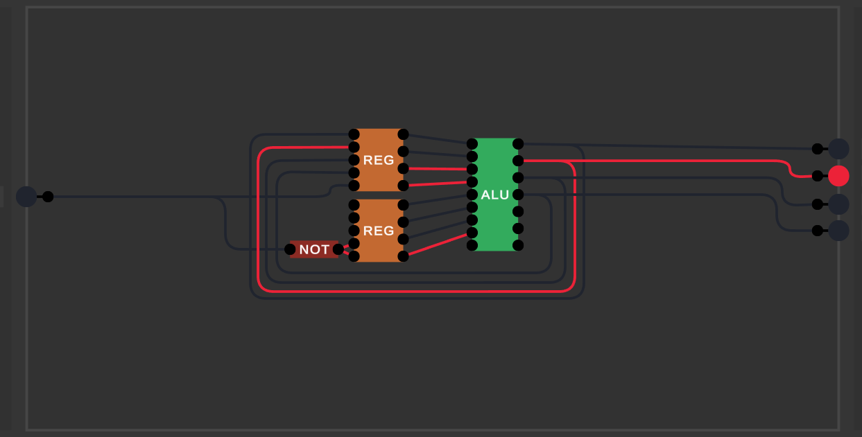
I tried way too many different ways to get this clock to work, and i'm sad that I used 2 hours of my time when the answer was as simple as adding a NOT gate.
The reason the NOT gate is connected is the sim has a hard time running logic to something if its not connected with an input, but it works.
EDIT: Here is a working example of the clock.
A pulse pin would be great!
?
I'll see if i could make a pulse. I need to figure out how to detect a falling edge of the clock. if you have any suggestions, that would be good.
My original idea was a pin that is a kind of a push button (monostable instead of bistable) so you could pulse mechanism with one mouse press instead of two (also sorry for late reply, but notification system refused to notify my about replies)
this is really interesting but I think you should add a way to delete projects
This is totally awesome, and definately has the potential to be one of the best logic simulators out there (especially as it's free).
A few suggestions (to help you make it the best):
-A way to snap wires to go either vertical or horizontal, maybe by pressing ctrl.
- A way to edit and delete chips you made previously.
- Some way to get more space such as zooming or moving the work area.
- A way to group wires and inputs into a single wire or bus line.
- A decimal representation of negative numbers.
- Moving the mouse over a chip input shows the input name.
Also there is no decimal representation of outputs, and the input names don't show.
Something else that might be interesting is adding a simulation rate to slow down the speed like you demonstrated in the "How do computers remember" video.
I'm excited to see where this project goes. Keep up the good work.
the first suggestion is already bound to [SHIFT]. jsyk :D
Oh, my bad. I wish I had known that sooner, my circuits would have been a lot neater.
hey man, i love your program. I have a suggestion I think you should add to the list of request (sorry) is a way to get the binary output in numbers, like you have in your second screen shot [the one with the ALU].
also maybe add hover text to the nodes? cause when i create a chip, like the alu, the next day I might not remember which node is the carry, negative, and zero nodes.
Use + and - while hovering on the input/output bars, it'll create a group of pins which have a number displayed (only positive ATM)
Well I've got myself a new addiction... I made an addressable 4-bit register, first time I clicked Create it didn't work so I rebuilt it and it worked somehow. Amazing software :)
Suggestion (that I haven't yet seen): allowing to increase the height of the chip bar, instead of having to scroll
A 7-segment would also be lovely, but I understand that'd require quite the rewrite especially if inside circuits :p
EDIT: I managed to build a 6 bit x 6 bit multiplier, with 12-bit output, made with no less than 11 4-bit binary adders and a mess of wires :D
thats so cool!!
It would be nice to have a screen with all the controls and that type of stuf
I found a bug where I have the two ghost pins that don't work and can't be deleted or changed but for some reason this only effects the project I use the most.
hey, i expericenced this too, if you exit and go back to it, i should be working again. if that doesn't work, close the program and reopen it.
is there anyway to edit the gate that you just made to the point that you can see all the things you did
Not yet, but I do plan to add a chip editing feature. Just need to figure out the details with what happens in places where the chip has been used, and now after editing potentially has more/fewer inputs or outputs.
i don't know how to make games, so take this with a grain of salt.
what if you had a refresh button. when clicked the system takes a moment and numbers all the wires, inputs, and outputs. After doing so it sets a 3rd value that says this node is connected to these nodes, and here is the wire data as well. Then after its mapped your board, it the recalculates the new nodes and the sizes of the chips.
then when its done refreshing, it displays the changes.
ok sounds good :)
EPIC TOOL. Suggestions tho:
Maybe a way to edit, delete, or preview chips, like for example hovering over the chip in bottom bar while holding alt will show a preview of the wirings inside. I kind of mess up some of my NOR and NAND gates and all I can do for now is either create a new project or go into the save file and delete the component there.
Looking forward to the video series and improvements to this tool!
Thanks! Will try add those things when I have some more time to work on this.
What's the setup like if one wanted to play around and try to add their own custom features? I've never really dabbled in modding or with unity, so any and all advice/help would be amazing. I've been looking through the source code but I assume a lot of the important stuff I was expecting is handled on the unity side that I can't see. (Edit: I should clarify that I'm fairly experienced programming wise, particularly with C#)
How do I find the save file? I really want to have a look at it.
i download the game from itch.io (HERE) not the source code but how do i run the source code? (also the tip did not work....)
Love this tool! It's super useful. I've got an idea you might want to implement: when creting more than one input/output it adds a decimal representation next to the inputs/outputs, however the number represented is always positive. How about adding the possibility of it being negative without having to have an extra bit to represent its sign? The numbers for 4 bits would be as follows, and I am sure you can deduce how it would be for a bigger o smaller number of bits.
I think it would be a great improvement because with this system you don't have to create special units to work with negative numbers, instead you only have to rethink the way you read the numbers.
Once again, amazing tool, and thanks so much!
Happy you like it! Will add a two's complement option when I have some more time to work on the tool.
How do you create the input and output I'm very confused.
it will be cool if you can snap the selected input/output in a grid when you press a button. Anyway this is very cool :D
I want to state how much I absolutely love this program even though it is nowhere near finished, I have been searching for a program like this that just gives you total freedom rather than a rigid step by step program
If you indend to update and continue this (which I really would love) I believe that the next thing you should look at is better organization of the created circuits visually; maybe something like a file system or at least separate custom groupings. Also the ability to delete types of circuits would be nice altho probably very buggy
If people want premade chips and so on there is a program called Logisim
How do i add input buttons and output lights?
I sooooo want to play with this but I keep getting "download forbidden" :(
Try to download it from the Itch.io app and if that doesn't work try a different browser.
see comment here: https://itch.io/post/2265443
is now a good time to say thanks, lol
Thank you so much for this tool, it's a very nice idea to combine a bunch of logic into a chip for easier use later, it makes things very simple.
Feature Request:
Deleting/Editing Schematics.
I accidentally made a mistake with a component that I wanted to correct. The only way to do this from within the program itself is to start a new project.
Oh boy, I certainly wanted to play around with this!
man... this is brand new; many expectations for this project!! i will be watching and hoping for best; good luck :)))
Is it some way to get the negative numbers on the side display like you had on the video?
In the instructions it says there are bars on the left and right to add inputs and outputs but they don't show for me :/
(i'm on mac and i downloaded it using the desktop app)
I've made a change to try fix this, could you please download the latest version and try again?
i realized that because i have a 1680x1050 screen, the bars were off the edge, and nothing's wrong with it. (wow i feel dumb lol)
Nah that's my bad, I should have set it up to handle different aspect ratios properly!
this is so great! already excited to be able to "edit" existing chips :) I followed along with both your videos and made the little 4-bit counter. excited to see where you go from here! :D
Could there be a windowed mode? I would like the ability to view documentation online while using the program.
I doesn't run on Mac OS Catalina
Could you try downloading again please, I've made a change that'll hopefully help. You'll need to open it by right clicking > Open (not double-clicking) then it should give a warning, but allow you to open anyway. Alternatively, if you download it via the itch.io app (https://itch.io/app) it'll work fine.
I can't figure out to run it, can anyone help? I have unity installed but see no way where to run.
After unzipping the files open them and go to: Digital logic sim (whatever operating system you're using) -> Digital logic sim, then open Digital logic sim.exe