If wires could be combined at the output of a gate like it would at the inputs, then OR will be the simplest gate of the Sim.
Its a headache to use OR every time I want to combine 2 wires at the output. It would be nice if we could combine the wires at the output. Pls add some code that would OR all the wires that are intersecting at the output.
P.S. I'm a university freshman, and I don't even have pocket money. And the best I could contribute to you is through Brave's BAT [I sent u 10]. Amazing work!
Sometimes modules that work in design phase might be dead after you create them. You need to do whole design phase all over again. Here is an example of that happening twice in a row.You can see the module named "INCREMENT" became dead and I created the same module as "INC" at the very begining of the video. then I design and test "PCOUNTER" module. Unfortunitly that died after creating as well.
I recorded this with nvidia shadowplay so only a small portion of designing "INCREMENT" module is here at the begining. actual length of this video is 20min.
I was very busy today I couldn't write a respond I'm sorry about that.
Since I'm a highschool graduate who prepares for local univercity exam I haven't taken any lessons other than my own reading and research. With my knowlage I designed a circuit and a language for it in previus days.
I have read everyhing you said many times yesterday. Pretty much everything you said was completely new to me. Now I need to rework my circuit and language design.
Neither the circuit nor lanugage is mature yet but I want to share some papers with you to give you some idea how it looks like.
Your info really helped me improve ALU. Thank you very much for your effort. Being in a cominity really helps people to improve in a topic so just like you said, I look forward to start a discord comminity too.
well I’m not a master at it I learned all my stuf from YouTube and Minecraft red stone if you whant I can show you the Minecraft tutorials to understand how the cpu works or I can draw the basic layout of a Alu and cpu
I'm loving this simulation, but I found an experience breaking bug that happens when you names 2 chips the same thing. It reverts the save to a former state and doesn't save any progress from that point forward. Hope this helps others avoid this.
I just finished ALU and RAM. I'm now very close to finally be able to run this cpu. When I finish I want to share the files here. I have spent about 12 hours now on this simulator and I haven't noticed any bug. Just be careful when you delete modules from %appdata% since if you delete a module that you forgot you used in another module previusly working parts that contained removed module will stop working with no notification. Biggest drawback is the fact that we have limited area to work on but I feel like I got used to it after the first 5-6 hour. My previus comment was about clocks but you can make clocks with adjustable frequancy and pulses with different durations. adjusting them is not that ideal but I don't think anymore that is a problem since I never used a clock or pulse so far. Obviusly I need at least one clock but I belive a manuel input would be actually better then a clock module. That way I can use a autoclicker and be able to preciesly change frequancy.
half of an adder with a normal Exclusive ORthis is a interesting X-OR this one can cancel out the x-or function and turn into a normal Or and there are other ways to cancel the xot function but the one here basicly shows you how it’s doing itan full adder using the normal x-or and special x-or and 2 other functions the FC and can look unless due to the OR but the CIN only for carry wile Flood Carry turns on all the carrys at once. edited ok to fix this make shure you make the OR function cancel out the AND gate in the picture below.a group of full adders the Carry out (COUT) is connected into Carry in as a carry to each Full adders except for one thats connected as a function the FC is connected to ALL the FCs of the full adders and OR function is connected to all Full adders too. also known as a Ripple carry adder (RCA) the slowest type of adder out there but good for beginners.inverters basically can take a binary input and flip it. like 1001 to 01101 to 2 inverters are required i prefer 2. one Ripple carry adder and other outputs this time which is the Zero flag (Fz) and the negative flag (Fn) and 2 new inputs for input a and b with all these functions you can add and subtract in binary and do basic logic like NOR, X-OR, AND, OR, NAND, and X-NOR. the reason why not is not in the list be because you can do NOT function but Nor hastily dose the exact same thing so its one less peace of programming you have to worry aboutthats all the basics of the ALU hope you enjoy the info.
I found the same sizing issue as you and I have made a version 2x smaller(or bigger depending on how you look at it). so far as I know there are no bugs with my version. I will try to upload it to GitHub.
This is had a lot of potential i think it can teach kids easily and can help intermetait or advanced people design Full blown CPUs. yes its still in beta but i think this simulator is very good and i love it
but i do see some problems thats very simple and prob be the first things fixed or added for next update.
This was exactly what I intended to develop myself for my project. I found this completely randomly while surfing through the internet and this maked me so happy. Thank you very much.
Edit: This lacks capasitors and resistors. If you don't want to implement simple physics even a hard-coded clock module(just like "and" and "not" modules) would work. or maybe an option for imputs to work like a clock with adjustable frequancy. Any of these would greatly improve this app.
Edit Edit: I managed to make a clock with xor gates but frequancy is depent on the update rate of simulation so you cant change it.
You could slow it down by creating a counter and then use the counter to time a latch with the most significant bit tied to the data, so that it is turned on and off as a square wave. You'd still be tied to the refresh rate, but you could use that to easily drive a power of two slow down rate. With a more complicated timer you wouldn't have to limit yourself to powers of two and the latch isn't completely necessary, but it would be the "right way."
It's called Digital Logic Sim for a reason, it simulates digital logic, not capacitors and resistors. I know why you might want them, but it's not an electricity simulation, it's for logic.
Jesus christ, 16 bytes is entirely plausible for this game. The screen size isn't that small, and you could fit smaller units in, and then combine them and use a demultiplexer to select between the addresses.
You can allow us to put more than 8 inputs and some way to zoom in and out, and so the inputs Will be more tiny and it would fit in the display.
It also would be Cool adding some form of compacting the wires in just one. My suggestion is when You click in an input it creates a wire and when You click in another input without distroying the other wire it Will create a group of wires in just one. And of course a way to compact inputs of a gate, does that make sense for you?
But there is no OR gate at the start so you need to make one but when i try it dosent let me (as above) connect in 2 inputs to 1 outpuf is not possible thus i cant make the gate
Okay, screw my godforsaken senseless abandoned upcoming Scratch project, everybody should just use this instead.*
I only have one problem though: if they rely on electrical signals to maintain data, doesn't that mean a depleted battery will completely reset the data storage?
Oh and I didn't download it yet. Am about to do that now
Yeah you should give me the ability to edit and delete chips and projects because I have one of each that says "uuuuuuuuuuuu" also slowing down time like in the videos
*nvm I heard Logisim is better but obviously more complicated
Having constants (high and low, think a chip that only has an output that is either on or off) would be nice. I tried making one out of a NOT-gate but the chip didn't output a high signal.
As far as I can see, there is no way to edit or delete blocks once you create them. There is also no way to delete a project. If I accidentally make a block incorrectly there is no way to fix it. I just have to live with a useless block in my toolbar. It would also be cool for the toolbar to allow you to organize it. For example, being able to keep the basic logic separate from more complicated blocks like adders or latches.
While yes there is no official support for that yet, a solution for that is to go to "%AppData%\LocalLow\Sebastian Lague\Digital Logic Sim\SaveData\" and there you can find your projects and the chips you made in them.
You need to press +/- while hovering the bar, before clicking. The "pin overlay" will reflect the change and when you actually click you will insert the right number of pins.
Hey! As far as I know, a RAM uses an index or an adress or whatever you call it. That means that the 64bit are split up into eight 8bit registers. That way, you need:
8 bits data 3 bits index 1 bit store 1 bit clock
This gives you a total of 13 inputs. And it actually has 13 inputs, not 14
I love this but there are 4 things I'd love to see in the future:
Grid snap, even with SHIFT being able to create straight lines I struggle to make it look good. Maybe having the grid line up with the size and spacing of the nodes on functions.
A controls screen. I was able to figure out all of the controls after a while of playing and reading comments but I feel that the instructions page should explain that to make things easier for new users.
Deleting, editing and previewing functions. I know this has been said a lot already but I still agree that it should be added.
Finally, I'd love to only have to right click to delete things. As said by someone else, it's weird reaching over to the other side of the keyboard just to delete something.
← Return to game
Comments
Log in with itch.io to leave a comment.
this is really slow on mac,
82% cpu
It would be interesting to see this simulator for android
Its uncomfortable to play on PC without zooming. Android gameplay would be worse.
I'm having a bug with the data latch. If you make it into a chip, it doesn't function correctly in chip form.
you are BEST!!! How do I make simple CPU
I recommend you to watch ben eater's tutorials. https://www.youtube.com/playlist?list=PLowKtXNTBypGqImE405J2565dvjafglHU
who here wants to start a discord community?
it would be nice
lets do it
ok what’s your discord name so I can send a link to you to the discord server
Furkan#8728
i sent it
Can you post the invite link here so everyone can just join?
Foxfire_13#9726
i sent it
https://discord.gg/9BQRzfqX
make an invite that doesnt expire pls
btw, 29#1731 is my discord pls send me an invite
to do so i need to set up a bot that delete and sends a new message for the links and links expire every 24 hours for discord
most of the computer logic I learned is from minecraft lol
you mean redstone???
I know this is old, but I wanna say you come across as a dick here. You knew, and they knew, exactly what they were talking about.
If wires could be combined at the output of a gate like it would at the inputs, then OR will be the simplest gate of the Sim.
Its a headache to use OR every time I want to combine 2 wires at the output. It would be nice if we could combine the wires at the output. Pls add some code that would OR all the wires that are intersecting at the output.
P.S. I'm a university freshman, and I don't even have pocket money. And the best I could contribute to you is through Brave's BAT [I sent u 10]. Amazing work!
it will be shorted , and it wont work properly in real life ,
Sometimes modules that work in design phase might be dead after you create them. You need to do whole design phase all over again. Here is an example of that happening twice in a row.You can see the module named "INCREMENT" became dead and I created the same module as "INC" at the very begining of the video. then I design and test "PCOUNTER" module. Unfortunitly that died after creating as well.
I recorded this with nvidia shadowplay so only a small portion of designing "INCREMENT" module is here at the begining. actual length of this video is 20min.
You should not use NOT gate by itself because it wont update and will always output 0 once you create a chip
I sent most of the information I know about basic ALUs did you find anything useful?
I was very busy today I couldn't write a respond I'm sorry about that.
Since I'm a highschool graduate who prepares for local univercity exam I haven't taken any lessons other than my own reading and research. With my knowlage I designed a circuit and a language for it in previus days.
I have read everyhing you said many times yesterday. Pretty much everything you said was completely new to me. Now I need to rework my circuit and language design.
Neither the circuit nor lanugage is mature yet but I want to share some papers with you to give you some idea how it looks like.
Your info really helped me improve ALU. Thank you very much for your effort. Being in a cominity really helps people to improve in a topic so just like you said, I look forward to start a discord comminity too.
well I’m not a master at it I learned all my stuf from YouTube and Minecraft red stone if you whant I can show you the Minecraft tutorials to understand how the cpu works or I can draw the basic layout of a Alu and cpu
Hi!
How do I find the save file on mac?
~Library/Application Support/Sebastian Lague/Digital Logic Sim/SaveData
What about for linux? (I know this is unrelated)
Does anyone know how to delete chips or entire projects? I have a few projects that are corrupted
C:\Users\user_name\AppData\LocalLow\Sebastian Lague\Digital Logic Sim\SaveData\project_name
Delete project
Or open project and delete chip, then open "WireLayout" and delete file with name your chip
The absolute Chad Guy Leroy created a version with an edit chip menu.
Here's the fork: https://github.com/gml16/Digital-Logic-Sim
Looks interesting, how do i compile it?
You load it on Visual Studio Code and spend the next followinghours understanding how to compile a JAR file.
Or, you write an email to the guy, like i did, asking him to make a compiled release!
I'm loving this simulation, but I found an experience breaking bug that happens when you names 2 chips the same thing. It reverts the save to a former state and doesn't save any progress from that point forward. Hope this helps others avoid this.
I just finished ALU and RAM. I'm now very close to finally be able to run this cpu. When I finish I want to share the files here. I have spent about 12 hours now on this simulator and I haven't noticed any bug. Just be careful when you delete modules from %appdata% since if you delete a module that you forgot you used in another module previusly working parts that contained removed module will stop working with no notification. Biggest drawback is the fact that we have limited area to work on but I feel like I got used to it after the first 5-6 hour. My previus comment was about clocks but you can make clocks with adjustable frequancy and pulses with different durations. adjusting them is not that ideal but I don't think anymore that is a problem since I never used a clock or pulse so far. Obviusly I need at least one clock but I belive a manuel input would be actually better then a clock module. That way I can use a autoclicker and be able to preciesly change frequancy.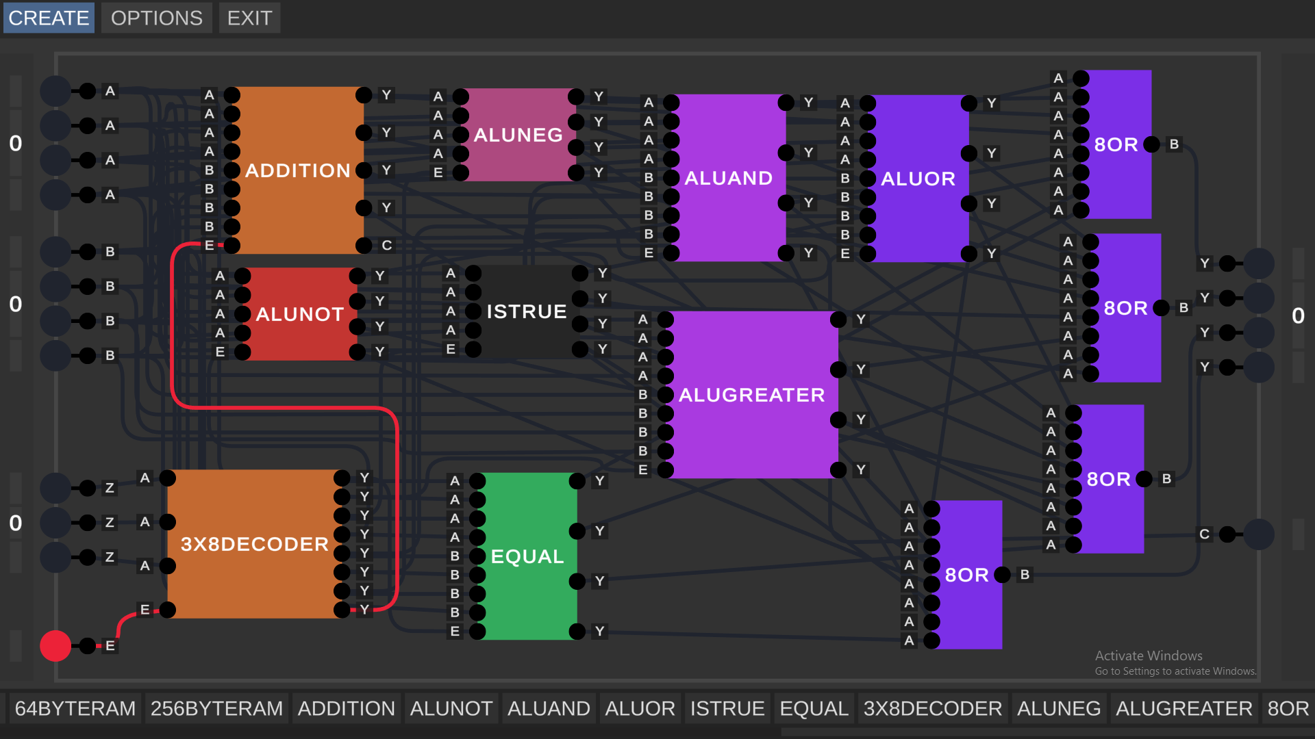
Dude, you're nuts. (good nuts)
kodbilen can i show you an easier way to use ALUs without making multiple different ALUs with different functions
Sure, of course I would love to learn. You might write or share material as a reply to this comment.
half of an adder with a normal Exclusive OR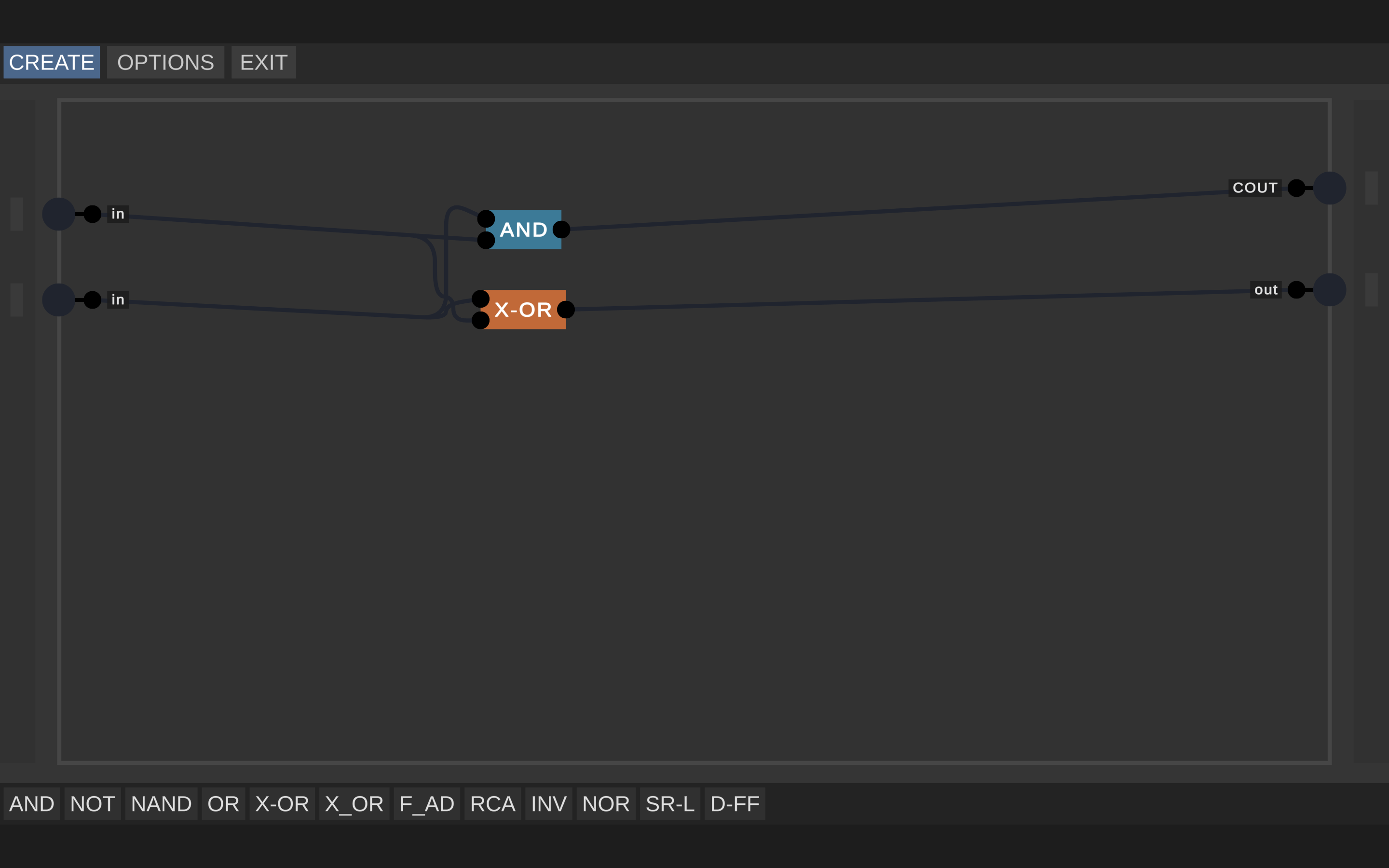 this is a interesting X-OR this one can cancel out the x-or function and turn into a normal Or and there are other ways to cancel the xot function but the one here basicly shows you how it’s doing it
 an full adder using the normal x-or and special x-or and 2 other functions the FC and can look unless due to the OR but the CIN only for carry wile Flood Carry turns on all the carrys at once. edited ok to fix this make shure you make the OR function cancel out the AND gate in the picture below.
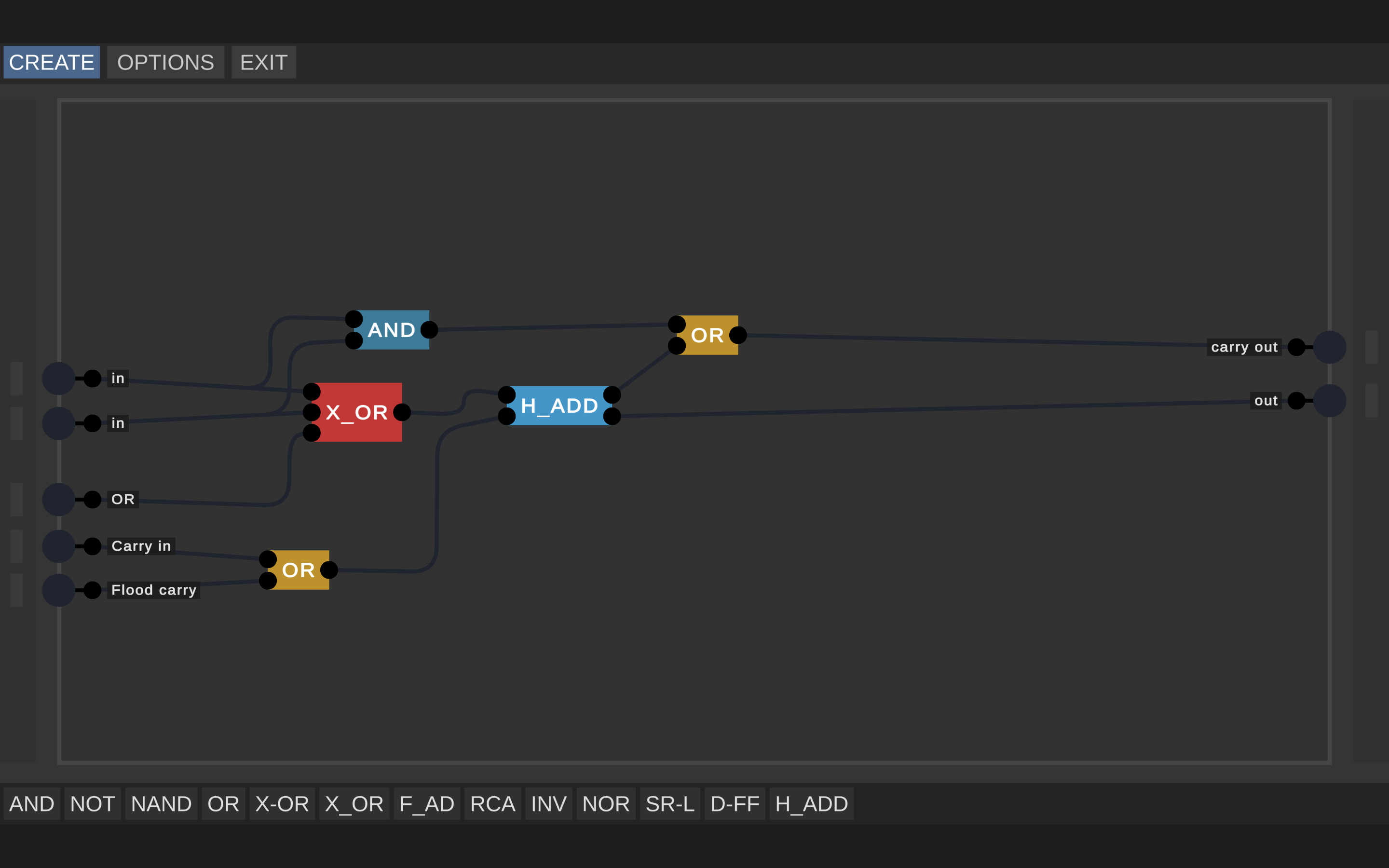 a group of full adders the Carry out (COUT) is connected into Carry in as a carry to each Full adders except for one thats connected as a function the FC is connected to ALL the FCs of the full adders and OR function is connected to all Full adders too. also known as a Ripple carry adder (RCA) the slowest type of adder out there but good for beginners.
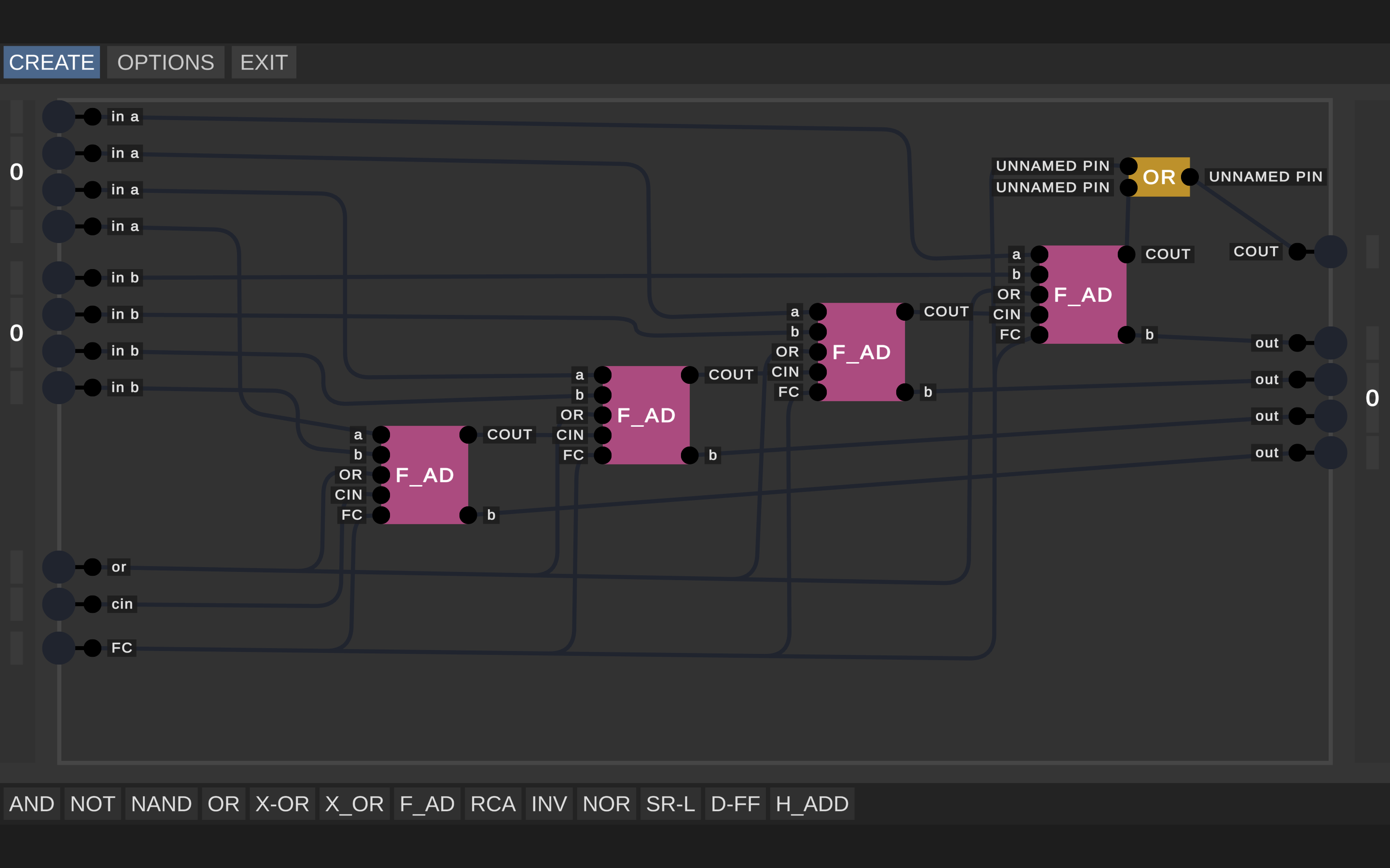 inverters basically can take a binary input and flip it. like 1001 to 0110
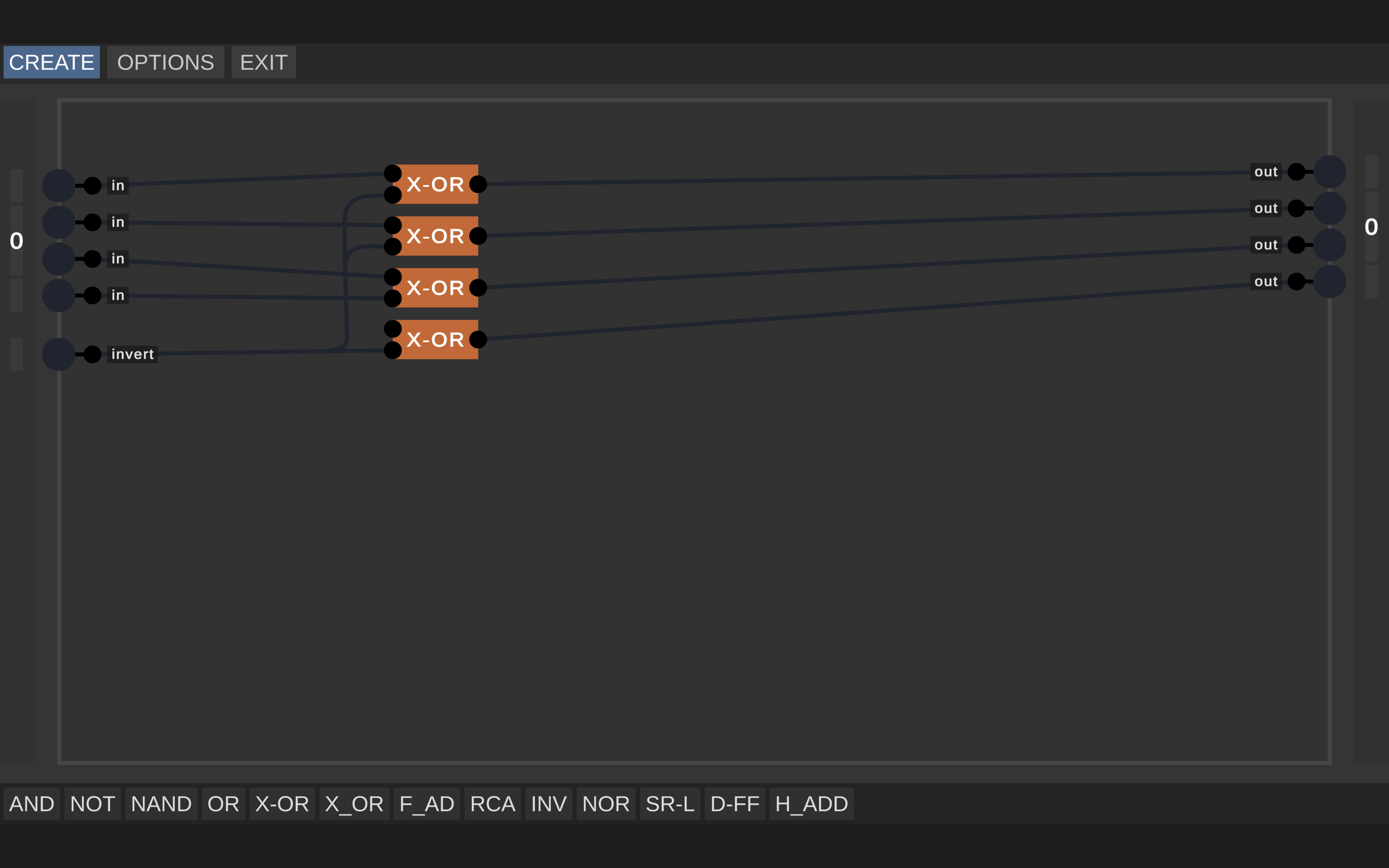 1 to 2 inverters are required i prefer 2. one Ripple carry adder and other outputs this time which is the Zero flag (Fz) and the negative flag (Fn) and 2 new inputs for input a and b with all these functions you can add and subtract in binary and do basic logic like NOR, X-OR, AND, OR, NAND, and X-NOR. the reason why not is not in the list be because you can do NOT function but Nor hastily dose the exact same thing so its one less peace of programming you have to worry about
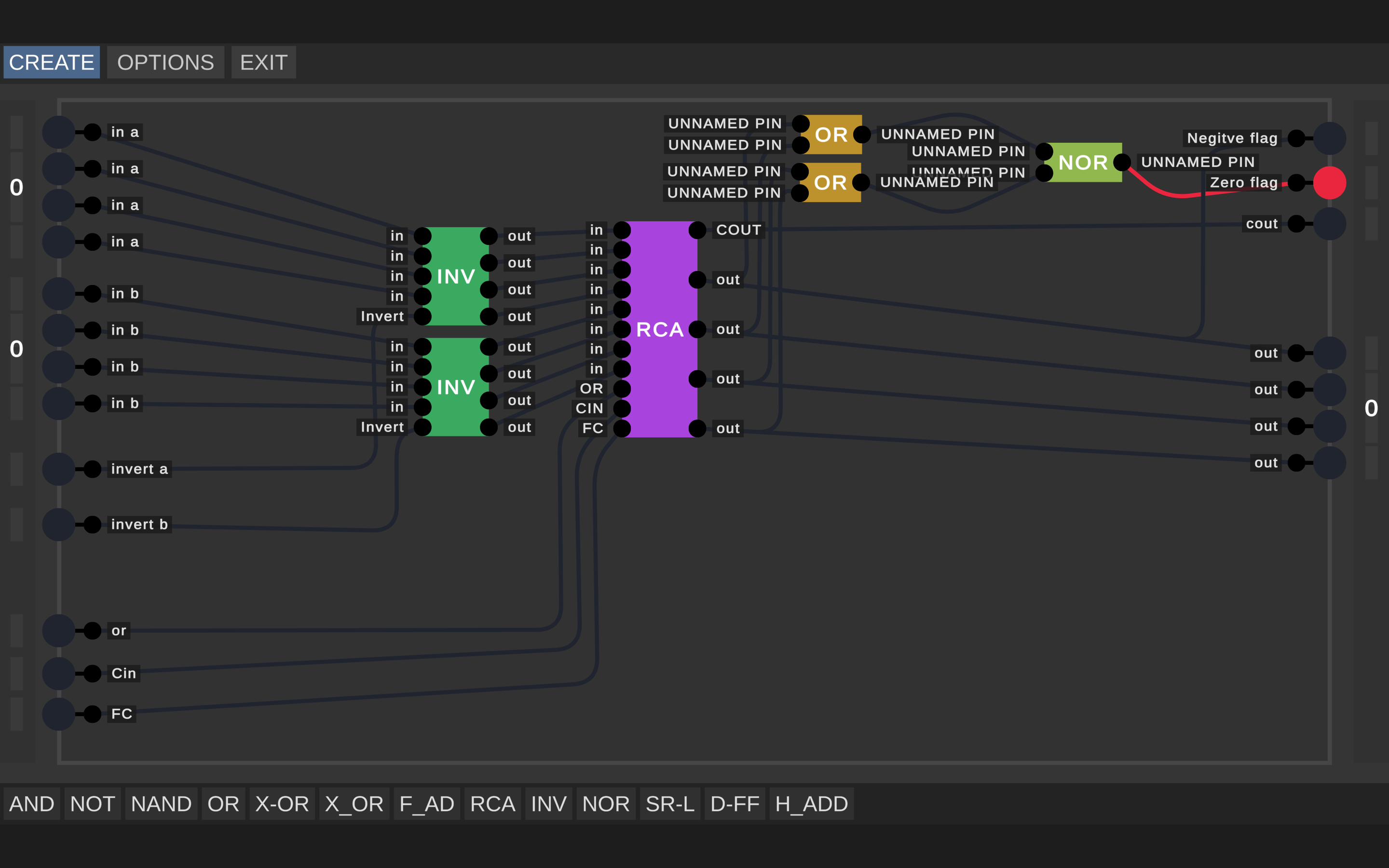 thats all the basics of the ALU hope you enjoy the info.
the Arithmetic logic unit
its in options at the top right between create and exit
Oh thanks also I can’t figure out how to make RAM
edit: figured it out.
I found the same sizing issue as you and I have made a version 2x smaller(or bigger depending on how you look at it). so far as I know there are no bugs with my version. I will try to upload it to GitHub.
Can someone please tell me the controls :~;
you can read instructions at the main menu.
Holy crap one terabyte man i just started making 1 kilobyte
and its 8 bit
i made 1tb with memory in this game
will try to make computer processing unit in this game from a ibm pc jr
but need to had selector chip so making 2 tb is easy and add screens to please
I use 256byte*4bit ram and even it makes considerable amount of lag how do you run that without lag issues.
my pc fastttttttttttttttttt
it can run cyperpunk 2077 on 8k 30fps
and 4k 120fps
1 tb!!!!!! can make 1 pt I mean petabyte??????
In theory yeah, but if you don't have an absolut unit of a pc the game will probably crash.
Probably but ill try
You don't know how big 1 terabyte is. In this game, it's hard to get one kilobyte.
This is had a lot of potential i think it can teach kids easily and can help intermetait or advanced people design Full blown CPUs. yes its still in beta but i think this simulator is very good and i love it
but i do see some problems thats very simple and prob be the first things fixed or added for next update.
This was exactly what I intended to develop myself for my project. I found this completely randomly while surfing through the internet and this maked me so happy. Thank you very much.
Edit: This lacks capasitors and resistors. If you don't want to implement simple physics even a hard-coded clock module(just like "and" and "not" modules) would work. or maybe an option for imputs to work like a clock with adjustable frequancy. Any of these would greatly improve this app.
Edit Edit: I managed to make a clock with xor gates but frequancy is depent on the update rate of simulation so you cant change it.
i thought the exact same thing when i i first started playing the simulator except for compacitors and resistor
You could slow it down by creating a counter and then use the counter to time a latch with the most significant bit tied to the data, so that it is turned on and off as a square wave. You'd still be tied to the refresh rate, but you could use that to easily drive a power of two slow down rate. With a more complicated timer you wouldn't have to limit yourself to powers of two and the latch isn't completely necessary, but it would be the "right way."
It's called Digital Logic Sim for a reason, it simulates digital logic, not capacitors and resistors. I know why you might want them, but it's not an electricity simulation, it's for logic.
i created 2 bytes of ram lmao
and it's banked now
i am having fun with this
i made 3 gigs of ram and i can go further
how do you make ram?
basically like making storage but making it work differnt havent tried it
No, no you didn't. 1 gigabyte is huge compared to 1 byte.
1 gigabyte is ~1 billion bits.
1 byte is 2 nybbles.
1 nybble is 4 bits.
also people who suggest stuff
please dont recommend something that has been recommend a million times
Reccomendations should go in the issue section of the github:
https://github.com/SebLague/Digital-Logic-Sim/issues
This is awesome! Your videos are very informative.
However, it would be great if we could zoom out and pan the camera. Maybe let us delete and edit gates. Also, coloring wires would be cool.
Since you can import chips by adding text files to the save data, I'm interested if there is a community of chip makers out there.
Yeah yesterday I did a 16 bytes ram. Thats pretty cool
it would be too big, that's false
or send me a vid to prove that
Is completely possible
send proof
my discord is Frostie#8802
Jesus christ, 16 bytes is entirely plausible for this game. The screen size isn't that small, and you could fit smaller units in, and then combine them and use a demultiplexer to select between the addresses.
Always have been. :D
You can allow us to put more than 8 inputs and some way to zoom in and out, and so the inputs Will be more tiny and it would fit in the display.
It also would be Cool adding some form of compacting the wires in just one. My suggestion is when You click in an input it creates a wire and when You click in another input without distroying the other wire it Will create a group of wires in just one. And of course a way to compact inputs of a gate, does that make sense for you?
Its nice exept one thing...
When i try to make an or gate or connect two inputs to one output it dosent let me
Can somebody help?
One workaround is to just use an OR, this will do the same thing
But there is no OR gate at the start so you need to make one but when i try it dosent let me (as above) connect in 2 inputs to 1 outpuf is not possible thus i cant make the gate
you would use NAND gates which are made from an AND and a NOT. And NOT gates.
Line one to NOT one. Line two to NOT two. And both those outputs to the NAND.
Or just watch Sebastian's video ;)
thanks!
This would actually short irl. So we just create an or-gate by inverting the inputs into an and gate and then inverting the output.
- Nand ┐ ├ AND - NAND - - Nand ┘what do you plan to do first? a video or an update
just asking
It would be great to be able to edit gates/chips after creating them. This has been asked by a few people below so thats a +1 from me also. Thanks!
anyway to delete a gate
no but i think you can do it by messing around with your save
here i found it https://itch.io/post/228387
add some sort of a tutorial instead of rules so new people can learn how it work
ahh they are doing it on their youtube
no for the controls
Okay, screw my godforsaken senseless abandoned upcoming Scratch project, everybody should just use this instead.*
I only have one problem though: if they rely on electrical signals to maintain data, doesn't that mean a depleted battery will completely reset the data storage?
Oh and I didn't download it yet. Am about to do that now
Yeah you should give me the ability to edit and delete chips and projects because I have one of each that says "uuuuuuuuuuuu"
also slowing down time like in the videos
*nvm I heard Logisim is better but obviously more complicated
hey man, until official support come for deleting saves and chips, this is my temporary solution!!
Post by MrPlayerYork in Digital Logic Sim comments - itch.io
Post by MrPlayerYork in Digital Logic Sim comments - itch.io
I made a comment about this here ^^^
I tried to make an and gate with "infinite" inputs.
would take to long.
Having constants (high and low, think a chip that only has an output that is either on or off) would be nice. I tried making one out of a NOT-gate but the chip didn't output a high signal.
A suggestion besides wire locking what about a locking grid or grid in the back to line things up
As far as I can see, there is no way to edit or delete blocks once you create them. There is also no way to delete a project. If I accidentally make a block incorrectly there is no way to fix it. I just have to live with a useless block in my toolbar. It would also be cool for the toolbar to allow you to organize it. For example, being able to keep the basic logic separate from more complicated blocks like adders or latches.
While yes there is no official support for that yet, a solution for that is to go to "%AppData%\LocalLow\Sebastian Lague\Digital Logic Sim\SaveData\" and there you can find your projects and the chips you made in them.
Awesome. Thank you. I tried looking through the files but couldn’t find them.
couldnt find that (and my PC couldnt either) can you please help?
would you plan on adding display blocks.
e.g. a decimal display or something of that sort.
I will look into the source and try to make improvements but would really awesome :)
I cant start it. I don't know how.
Nevermind, I figured it out.
my only suggestion is can you make the chip area a tad bigger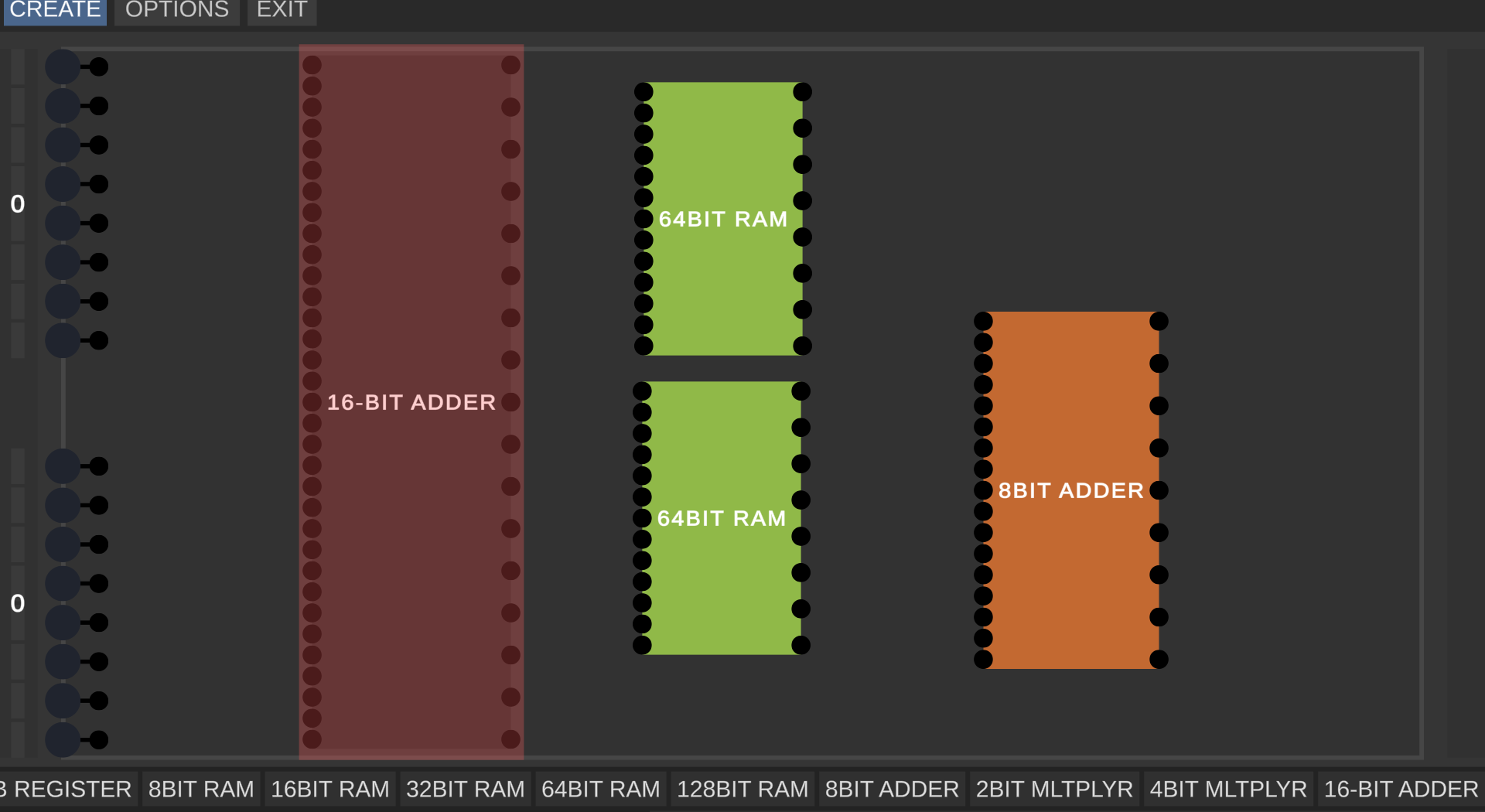
You need to press +/- while hovering the bar, before clicking. The "pin overlay" will reflect the change and when you actually click you will insert the right number of pins.
this is unrelated and im not critisizing you but how is that 64-bit ram?
i wanna know how to make it
there is just 14 bits
it would need 66 bits
64 bits the bits that you need to store
1 bit the clock
1 bit the store
so it isn't possible
Hey!
As far as I know, a RAM uses an index or an adress or whatever you call it.
That means that the 64bit are split up into eight 8bit registers.
That way, you need:
8 bits data
3 bits index
1 bit store
1 bit clock
This gives you a total of 13 inputs. And it actually has 13 inputs, not 14
sorry, i am an idiot furry and i forgot
I can't seem to save any of my chips :/ I was really looking forward to starting with this now
Lovely UI. I just hope this gets optimized for larger builds, my game crashed after building a 4-bit multiplexer.
Just do it in real life. Its so optimized, it can simulate 46.5 billion light years!
Take it as a nerd joke, OK.
I understood that.
IRL has a pretty descent rendering engine. Heard it can render something like 8k seemlessly for 8 Billion players at once.
I love this but there are 4 things I'd love to see in the future: