Oh how i remeber when pc was 32bit, IS ANNOYING ALL BEING 64Bit, So i gave up & today i use a 64bits pc.
The point internally (ironically this program explains the science behind of this) Your 32-Bits based devices will be obsolete on the year 2038aprox (Because some sort of overflow in the timer will be restart your time, its sounds meh; but look arond of the bug Y2K)
I just downloaded for mac high sierra version, and it is not working. I appreciate your efforts but I would recommend not requesting donations before users experience the software.
He took time out of his day to develop a program to help people learn and is distributing it for free but appreciates a donation. I used this exact program on Mac and it works. Posting comments like this will just make people distribute it for money without a free option.
Signal speed is constant. If you want to change it's speed, make easiest frequency generator by register, NAND-clock and adder. Fastest clock signal you can ever make in this game could be made by NAND-clock(I commented one guy's question about clock below, so I made there all of them I ever used [Sierpinski generator doesn't count, because I made it for fun]).
Thanks for the reply. Clocks are not a problem. I wanted to be able to show i.e. D-latch instability as in the video, with the signal propagating back and forth. Well, maybe in a later version then.
You can't delete projects and chips in game. All of them situated in: C:\Users\user_name\AppData\LocalLow\Sebastian Lague\Digital Logic Sim\SaveData on WindowsOS, and: /home/user_name/.config/unity3d/Sebastian Lague/Digital Logic Sim/SaveData for LinuxOS. They named similar as in game. If you want to edit chip, delete old one and make another one.
P.S. I really tired to answer similar questions about editing and deleting in this game. What's problem to read all comments below before asking your questions?
Yeah, that's true. Sorry, if I answered roughly. But, really, if you look below, every second comment tells about path to the game files, where all projects are situated.
I found that if you create another chip with the same name then exit and reenter the project then it automatically replaces the chip without saving the old one.
[CLOCK-makes clock signals, if input is "1"] [ON-constant "1" output] [GATE-lets inputs signals to output, if POWER input is "1"] [INC-increases binary input by 1] Register was made in dev's second video.
In results, we have 8 outputs, which switches on with different frequencies. Choose any you want.
I meant name of user of computer. For example, i have two users on my computer and both of them have radically different desktops and workplaces. I setted up this game on my main user space, so i need to find this folder on his space.
Inputs and outputs has decimal numbers, if you group them (up to 8 inputs/outputs in group). Also its possible to make them signed, if checkmark is on.
[CLOCK-makes clock signals, if input is "1"]
[ON-constant "1" output]
[GATE-lets inputs signals to output, if POWER input is "1"]
[INC-increases binary input by 1]
Register was made in dev's second video.
In results, we have 8 outputs, which switches on with different frequencies. Choose any you want.
Man, if you writing your game experience, please, press reply under your first message and make a column of your own comments. Don't clutter up with comments.
Chips must be connected to inputs and outputs. If you use NOT chip as source power without connecting to inputs, your chip won't work. Check your schemes for this mistakes and make sure it works.
If you need to create clock, which always generates signals, make OR chip, then create clock scheme with NAND chip, connect clock's input to OR output, then connect straight and inverted main input signals to inputs of OR gate. Then, there is no matter, what signal you use on main input. Main output will always clock.
It depends on how will you call new chip and which color you use while you create it. AND chip is default chip and it's color is light blue. It's situated on the left of chip list.
If you asking, how this game remembers chips, go to (if you use WindowsOS): C:\Users\user_name\AppData\LocalLow\Sebastian Lague\Digital Logic Sim\SaveData and find your chips there.
This app is awesome for learning basic Logic but it would be cool if you you could make a clock and then make it into a chip then you could make the circuit more compact, another thing if you could delete the chips without going into the file that would be cool. I will commit more if I find anything else that could be cool and good to help :D.
Clock could be made by logic. For example, simple one-phase clock looks like:
Two-phase clock could be made by getting second signal from AND-out (on picture i forgot to add AND operator, which connects to OUT1 in output and IN and AND's OUT. It needs to stop "constant 1" signal in output):
Also, you can make different frequencies generator by N-bit INC (increases binary number by 1) and N-bit REG (just register): [also on picture: ON(Makes 1 on OUT without care about IN {constant1}) CLOCK(Just first screenshot of my answer) GATE(Sends input signals{IN} to output{OUT}, if POWER is 1)]
I hope i helped to you with clock. Good luck.
P.S. I made this funny circuit that makes sierpinski triangle on truth table.
Every logic chips must be connected to inputs and outputs or other chips, which connects to them. Clock will not work, if you use NOT gate as source power without connecting to input. And it's a reason, why i made ON gate (constant 1, which made by connecting straigh and inverted signal from input to OR gate, and result connects to output).
Shift register is really usable for clock scheme, but most optimized clock made by NAND chip. My other examples are made on this basement, but all of them uses for different functional.
I think, that it's more easier, if you use your own names of chips, because there is a lot of standarts around the globe, where logic gates looks different.
I am very glad to use this program but I have a problem: where are the projects being saved once you create them?. I started one project and when I exited the progress has been lost. Then I wanted to delete the project but I didn´t find where it has been saved. Could somebody help me?.
If you still don't know where projects are saved (assuming you use Windows). It's C:\Users\user_name\AppData\LocalLow\Sebastian Lague\Digital Logic Sim\SaveData
Please add resitors red/blue/green/white LEDs and buttons you can place inside code, that your elements are in sidebar bigger limit for chip names RGB LEDs and more. ;D
There is no place for power sources, resistors and other electric components. This game made only for logic modulating and learning. If you want to modulate circuits, use circuit simulator like "everycircuit" and similar.
I absolutely love this program. I've always been interested in things like this but I've had a hard time learning it. your YouTube videos are amazing as well!
Unfortunately I've had a few problems with the program. the biggest issue is that seemingly randomly whenever i leave the program almost all of my work disappears :( Another issue is that sometimes the inputs and outputs get locked into place and un editable.
On another note there is so much room for new things. I'm not sure if you'd ever continue working on this (If you do that would be great) Id love to see an infinite work space, maybe some LEDS or LCD screens, or things like seven segment displays. Maybe some more room for different kind of inputs (Like a keyboard or stand alone buttons/Switches)
Thank You for putting the time in to make this program in the first place. it helped me learn alot.
It depends on the operating system you are using and how did you downloaded this game. I used itch.io app and runned this game from there. If you downloaded zip file, find executable file (it should be called Digital Logic Sim.exe on WindowsOS).
Has anyone found a way to edit chips that have already been made? I made a giant chip with lots of gates inside it, but then realized that something inside of it was wrong. Now I don't know how to edit and fix it.
If you want to change chips, you must know, where files are located. If you use WindowsOS, path will be: C:\Users\user_name\AppData\LocalLow\Sebastian Lague\Digital Logic Sim\SaveData
Then you can edit files. Better way to edit wrong chip is to make workable chip, copy it and then insert instead of not-workable chip. I hope, that i helped you. Good luck.
You say that to edit a wrong chip i should replace it with a workable chip. The problem is I spent an hour making this complicated chip which has lots of working parts inside of it, and i don't remember how I made it, so I can't just make a new one.
Well, it's not a serious project. It made for "How does computer works" video series. But then his subs asked to add his program from his video to itch.io. That's why it happened. A lot of bugs appeared because of low usage of this game.
Something else that would be nice is a chip editor just like the one in digital-logic-sim, where you can package up your circuits into a single chip. Also there should be multiple project save slots instead of a singular canvas that you can edit.
I’ll be trying to implement a blueprint system like factorio’s in tandem with drag select. I think that’ll be a good compromise. I’ll also look into save slots.
Yeah, sorry about that. The way that my game is rendered doesn’t really allow for other resolutions right now. I’ll look into it for the next update, but it’s very unlikely that I can make it work for every resolution.
I LOVE this as a learning tool! I just wish there was a way to go back and view, edit or delete circuits I've made. If that was added as a feature this would be perfect.
Idea: A pixel that turns off/on depending on whether or not it's powered, kind of like an output block you could put anywhere, this would allow 2d screens which would be cool.
You mean, like 7 segment indicator or garland? But how it would be displayed, if you create a new chip, which contains chip/chips with indicators? It's a good idea, but i can't imagine, how it should work...
So, it would be nice, if developer will add this function and will make 3rd part of "Exploring how computer works". He can tell about multiplexors, encoders, digital comparators and majority element.
how can i install this on my raspberry pi ( i am using raspbian AKA linux) i downloaded the linux one but it said " xterm no file or folder" plz some1 help
← Return to game
Comments
Log in with itch.io to leave a comment.
how do i open the app.
extract the zip to somewhere on your desktop open the folder and double click the .exe
Does anyone know how I delete created "chips" and project saves?
I can't understand question: are you asking how to delete or you can suggest another way to do it? If first, chesk this post:
https://itch.io/post/3024868
is there a 32 bit version? My pc is 32 bit
Oh how i remeber when pc was 32bit, IS ANNOYING ALL BEING 64Bit, So i gave up & today i use a 64bits pc.
The point internally (ironically this program explains the science behind of this) Your 32-Bits based devices will be obsolete on the year 2038 aprox (Because some sort of overflow in the timer will be restart your time, its sounds meh; but look arond of the bug Y2K)
i was using a 32bit os bc windows 10 is so bad to old machines that my pc cant handle the 64 bit win10 somehow, now i manage to change to linux
yoo is so hard to avoid 32bit if your pc is Phissically incompatible with him :U
if you want to use linux the problem is as well is stuck on your specific pc as 32 bit version
u an download the source code and build it for 32bit i guess
I just downloaded for mac high sierra version, and it is not working. I appreciate your efforts but I would recommend not requesting donations before users experience the software.
Thank you,
The donations are not required and you can't turn them off without removing the ability to donate entirely
He took time out of his day to develop a program to help people learn and is distributing it for free but appreciates a donation. I used this exact program on Mac and it works. Posting comments like this will just make people distribute it for money without a free option.
Thank you.
who is modder?
i dont understand how to add input or outputs how do u do it
To add itnputs/outputs press left-mouse-button on left/right side of the screen. To group inputs/outputs use + button.
This game is
addictingfunthis is not game , is just sim
also how do i make a decimal display like what was done in the vide
Answer is here:
https://itch.io/post/301361
It's five comments below.
how do i delete my custom chips like or gates because i made chips that don't work and i need to ether mod them or delete and create new ones.
https://itch.io/post/3020134
There is the answer (this post is situated 3 comments below yours).
and me
meu amigo, tem como fazer uma versão 32bit por favor
update or mode
Can signal propagation speed be adjusted?
Great project btw.
Signal speed is constant. If you want to change it's speed, make easiest frequency generator by register, NAND-clock and adder. Fastest clock signal you can ever make in this game could be made by NAND-clock(I commented one guy's question about clock below, so I made there all of them I ever used [Sierpinski generator doesn't count, because I made it for fun]).
Thanks for the reply. Clocks are not a problem. I wanted to be able to show i.e. D-latch instability as in the video, with the signal propagating back and forth. Well, maybe in a later version then.
How do I delete a project? How do I go back to a chip I messed up on to correct it?
You can't delete projects and chips in game. All of them situated in:
C:\Users\user_name\AppData\LocalLow\Sebastian Lague\Digital Logic Sim\SaveData
on WindowsOS, and:
/home/user_name/.config/unity3d/Sebastian Lague/Digital Logic Sim/SaveData
for LinuxOS. They named similar as in game. If you want to edit chip, delete old one and make another one.
P.S. I really tired to answer similar questions about editing and deleting in this game. What's problem to read all comments below before asking your questions?
Perhaps if the main content of the description mentioned then folks would know before even reaching comments.
Yeah, that's true. Sorry, if I answered roughly. But, really, if you look below, every second comment tells about path to the game files, where all projects are situated.
Hey wassup bro,
I found this location for linux..
/home/<username>/.config/unity3d/Sebastian Lague/Digital Logic Sim/SaveData
Good job. Thx.
And on the MacOS in:
~/Library/Application Support/com.SebastianLague.DigitalLogicSim/SaveData
thx i needed this
I found that if you create another chip with the same name then exit and reenter the project then it automatically replaces the chip without saving the old one.
can you make the delay of a clock slower?
Yes, you can.
Just make this scheme.
[CLOCK-makes clock signals, if input is "1"]
[ON-constant "1" output]
[GATE-lets inputs signals to output, if POWER input is "1"]
[INC-increases binary input by 1]
Register was made in dev's second video.
In results, we have 8 outputs, which switches on with different frequencies. Choose any you want.
How do i group up multiple Inputs and outputs to show binary like in the videos?
I just figured it out, press + before placing the input or output, I'm apparently very small brain.
How do I delete my previous projects?
You cannot :(
All projects are situated there (only for WindowsOS):
C:\Users\user_name\AppData\LocalLow\Sebastian Lague\Digital Logic Sim\SaveData
for linux, its
/home/<username>/.config/unity3d/Sebastian Lague/Digital Logic Sim/SaveData
Good job, man. Thx!
what did you mean on user_name
I meant name of user of computer. For example, i have two users on my computer and both of them have radically different desktops and workplaces. I setted up this game on my main user space, so i need to find this folder on his space.
my username on os?
Is there a way to edit an already existing chip
Unfortunately, you cannot
All chip files are situated there (only for WindowsOS):
C:\Users\user_name\AppData\LocalLow\Sebastian Lague\Digital Logic Sim\SaveData
You can delete your chip files, return to game and make another one.
Yo, can someone help me make a XOR gate and some other stuff please, my discord is danny06202#4017
Try this. It works.
thanks
why can't I also put numbers for the output for the 4bit adder
I can't understand your problem. Nothing interferes you to put inputs and outputs (at least on WindowsOS everything works correctly).
Use buttons "+" and "-", if you want to group inputs and outputs (check mark uses for showing binary number signed).
he mean in the official video is if Sebastian made an adder
will in binary number the left had a decimal number
Inputs and outputs has decimal numbers, if you group them (up to 8 inputs/outputs in group). Also its possible to make them signed, if checkmark is on.
Also is it possible to make a clock go slower
It's possible.
Just make this scheme.
[CLOCK-makes clock signals, if input is "1"]
[ON-constant "1" output]
[GATE-lets inputs signals to output, if POWER input is "1"]
[INC-increases binary input by 1]
Register was made in dev's second video.
In results, we have 8 outputs, which switches on with different frequencies. Choose any you want.
Can you help me, please??? https://itch.io/post/2699784
i made a clock
its simple but it works
Man, if you writing your game experience, please, press reply under your first message and make a column of your own comments. Don't clutter up with comments.
sry
i have a question when i put the clock i made into a chip it stops working do u know why
Chips must be connected to inputs and outputs. If you use NOT chip as source power without connecting to inputs, your chip won't work. Check your schemes for this mistakes and make sure it works.
If you need to create clock, which always generates signals, make OR chip, then create clock scheme with NAND chip, connect clock's input to OR output, then connect straight and inverted main input signals to inputs of OR gate. Then, there is no matter, what signal you use on main input. Main output will always clock.
i made a circuit that can compare two numbers or values with 4 bits
great sim btw
but you should don't add xor. add xnor
How does the program distinguish AND from NAND???????
It depends on how will you call new chip and which color you use while you create it. AND chip is default chip and it's color is light blue. It's situated on the left of chip list.
If you asking, how this game remembers chips, go to (if you use WindowsOS):
C:\Users\user_name\AppData\LocalLow\Sebastian Lague\Digital Logic Sim\SaveData
and find your chips there.
Graphically, there is no differences (2 inputs and 1 output), so call your chips correctly (also as short as possible).
I would love if you maked a android version
I would love it too, because my android device is more powerful than my laptop and i use smartphone more often.
hillarious design (y)
Nothing superfluous and nothing is overlooked. Minimalism in its purest form. I like it too.
wow, just wow, who ever created this.
thank you :)
This app is awesome for learning basic Logic but it would be cool if you you could make a clock and then make it into a chip then you could make the circuit more compact, another thing if you could delete the chips without going into the file that would be cool. I will commit more if I find anything else that could be cool and good to help :D.
Clock could be made by logic. For example, simple one-phase clock looks like: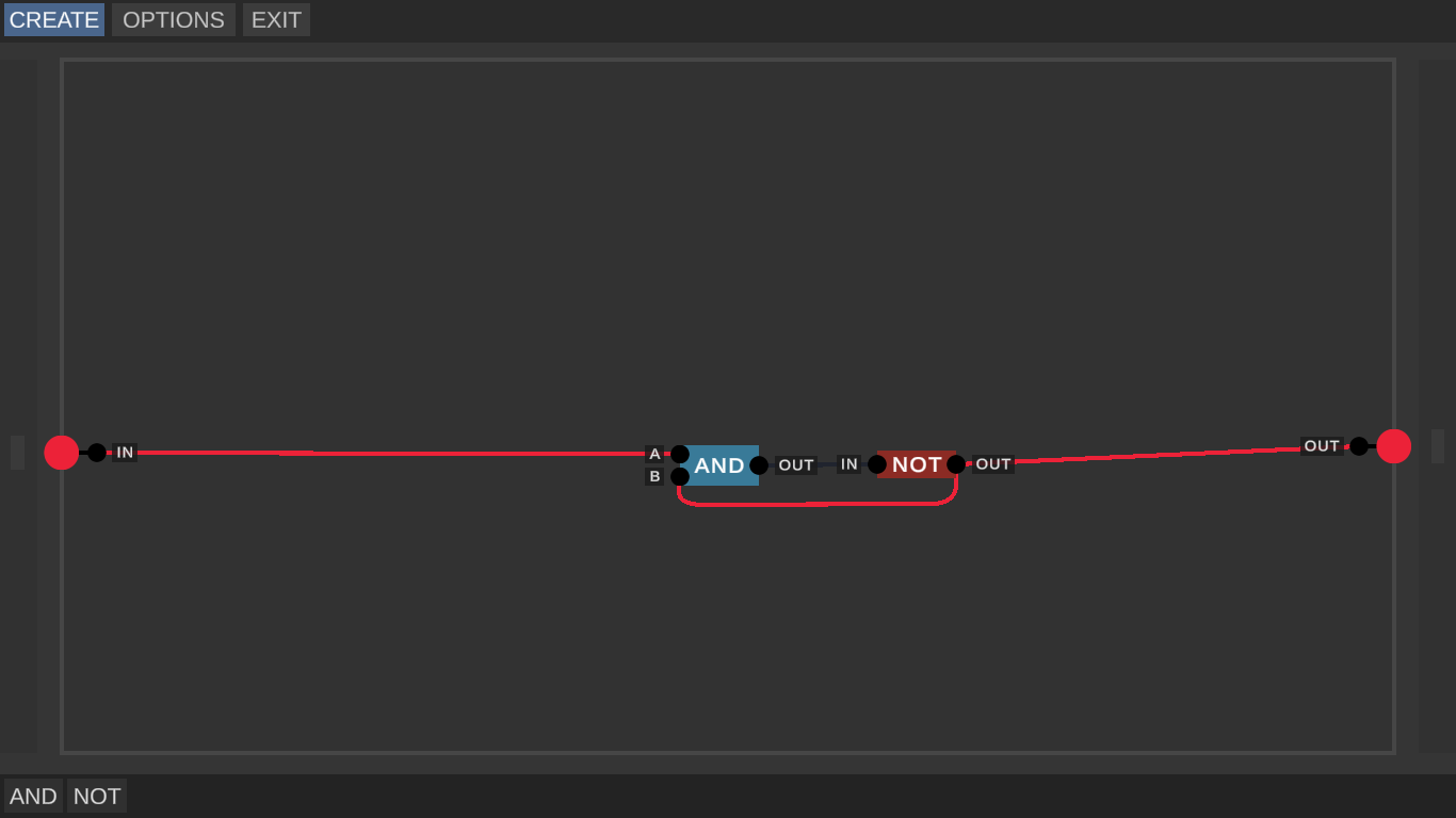
Two-phase clock could be made by getting second signal from AND-out (on picture i forgot to add AND operator, which connects to OUT1 in output and IN and AND's OUT. It needs to stop "constant 1" signal in output):
Also, you can make different frequencies generator by N-bit INC (increases binary number by 1) and N-bit REG (just register):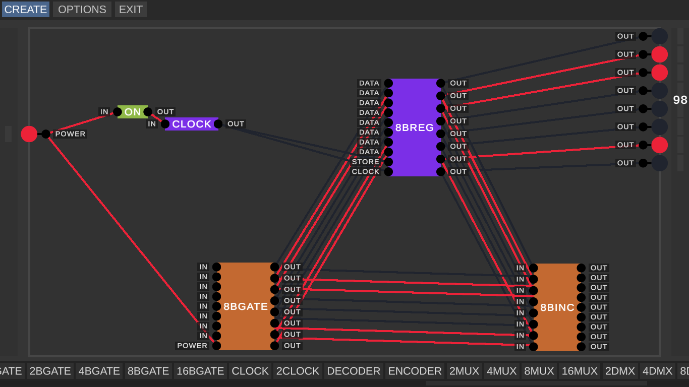
[also on picture:
ON(Makes 1 on OUT without care about IN {constant1})
CLOCK(Just first screenshot of my answer)
GATE(Sends input signals{IN} to output{OUT}, if POWER is 1)]
I hope i helped to you with clock. Good luck.
P.S. I made this funny circuit that makes sierpinski triangle on truth table.
I actually meant that for whatever reason, my clock circuits just don’t work.
Every logic chips must be connected to inputs and outputs or other chips, which connects to them. Clock will not work, if you use NOT gate as source power without connecting to input. And it's a reason, why i made ON gate (constant 1, which made by connecting straigh and inverted signal from input to OR gate, and result connects to output).
i commented a simple clock
btw u can use d flip flops to make clocks btw and wow ur stuff looks amazing
Thx, i tried my best.
Shift register is really usable for clock scheme, but most optimized clock made by NAND chip. My other examples are made on this basement, but all of them uses for different functional.
It's a great app! I suggest adding logic gates signs for easier recognition!
You mean, standard pictures of logic gates?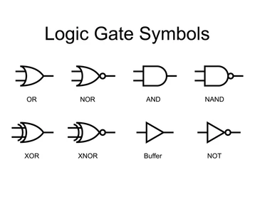
I think, that it's more easier, if you use your own names of chips, because there is a lot of standarts around the globe, where logic gates looks different.
I am very glad to use this program but I have a problem: where are the projects being saved once you create them?. I started one project and when I exited the progress has been lost. Then I wanted to delete the project but I didn´t find where it has been saved. Could somebody help me?.
If you still don't know where projects are saved (assuming you use Windows). It's C:\Users\user_name\AppData\LocalLow\Sebastian Lague\Digital Logic Sim\SaveData
thank you!
Please add resitors red/blue/green/white LEDs and buttons you can place inside code, that your elements are in sidebar bigger limit for chip names RGB LEDs and more. ;D
and also like that you can delete/edit/rename chips or projects, thats really annoying too
BUT MOST IMPORTANT CAPACITOR
There is no place for power sources, resistors and other electric components. This game made only for logic modulating and learning. If you want to modulate circuits, use circuit simulator like "everycircuit" and similar.
I absolutely love this program. I've always been interested in things like this but I've had a hard time learning it. your YouTube videos are amazing as well!
Unfortunately I've had a few problems with the program. the biggest issue is that seemingly randomly whenever i leave the program almost all of my work disappears :( Another issue is that sometimes the inputs and outputs get locked into place and un editable.
On another note there is so much room for new things. I'm not sure if you'd ever continue working on this (If you do that would be great) Id love to see an infinite work space, maybe some LEDS or LCD screens, or things like seven segment displays. Maybe some more room for different kind of inputs (Like a keyboard or stand alone buttons/Switches)
Thank You for putting the time in to make this program in the first place. it helped me learn alot.
Cant wait too see more from you! :)
and me
how do i run this game?
It depends on the operating system you are using and how did you downloaded this game. I used itch.io app and runned this game from there. If you downloaded zip file, find executable file (it should be called Digital Logic Sim.exe on WindowsOS).
thanks a bunch
absolute legend, im new to ichi.io and didnt know what to do(i used to app). thank you
Has anyone found a way to edit chips that have already been made? I made a giant chip with lots of gates inside it, but then realized that something inside of it was wrong. Now I don't know how to edit and fix it.
If you want to change chips, you must know, where files are located. If you use WindowsOS, path will be:
C:\Users\user_name\AppData\LocalLow\Sebastian Lague\Digital Logic Sim\SaveData
Then you can edit files. Better way to edit wrong chip is to make workable chip, copy it and then insert instead of not-workable chip. I hope, that i helped you. Good luck.
You say that to edit a wrong chip i should replace it with a workable chip. The problem is I spent an hour making this complicated chip which has lots of working parts inside of it, and i don't remember how I made it, so I can't just make a new one.
Sorry, man. Its inpossible to edit another way. You need to create another chip. ;(
oh ok. Someone that knows how to develop games in unity should read all of these comments and then make an updated version of the simulation
Well, it's not a serious project. It made for "How does computer works" video series. But then his subs asked to add his program from his video to itch.io. That's why it happened. A lot of bugs appeared because of low usage of this game.
https://aleainfinitus.itch.io/logistruct for anyone asking for infinite canvas.
Which version should I download?
0.4 is far more up to date than 0.2.1
ok
The game takes up only half of my monitor. (My monitor is 2k) Is there a way to set the resolution so the game takes up all of my monitor?
Also it would be useful to have a drag to select function, because right now the only way to delete a lot of stuff is clearing the canvas
Drag select is slated for the next update because it’s going to be pretty tough to implement.
Something else that would be nice is a chip editor just like the one in digital-logic-sim, where you can package up your circuits into a single chip. Also there should be multiple project save slots instead of a singular canvas that you can edit.
I’ll be trying to implement a blueprint system like factorio’s in tandem with drag select. I think that’ll be a good compromise. I’ll also look into save slots.
My monitor can't run your game because of fixed resolution 1920x1080. My monitor is smaller because i use laptop.
Yeah, sorry about that. The way that my game is rendered doesn’t really allow for other resolutions right now. I’ll look into it for the next update, but it’s very unlikely that I can make it work for every resolution.
Yeah i have this problem too
Ok, looking into it it might be possible to fix.
You can keep this resolution, but make full-screen scaling at least, plz.
Ok, looking into it it might be possible to fix.
I LOVE this as a learning tool! I just wish there was a way to go back and view, edit or delete circuits I've made. If that was added as a feature this would be perfect.
and infinite space and zooming
Idea: A pixel that turns off/on depending on whether or not it's powered, kind of like an output block you could put anywhere, this would allow 2d screens which would be cool.
You mean, like 7 segment indicator or garland? But how it would be displayed, if you create a new chip, which contains chip/chips with indicators? It's a good idea, but i can't imagine, how it should work...
So, it would be nice, if developer will add this function and will make 3rd part of "Exploring how computer works". He can tell about multiplexors, encoders, digital comparators and majority element.
The chip would have an array of displays at the end maybe? I didn't think this idea through too well.
how can i install this on my raspberry pi ( i am using raspbian AKA linux) i downloaded the linux one but it said " xterm no file or folder" plz some1 help